Parallel seawater desalination device based on ion concentration polarization effect
A concentration polarization and effect technology, applied in the field of parallel seawater desalination devices, can solve the problems of high difficulty, low extraction efficiency and high process requirements, and achieve the effects of high reliability, high efficiency and great feasibility
- Summary
- Abstract
- Description
- Claims
- Application Information
AI Technical Summary
Problems solved by technology
Method used
Image
Examples
Embodiment 1
[0029] Example 1:
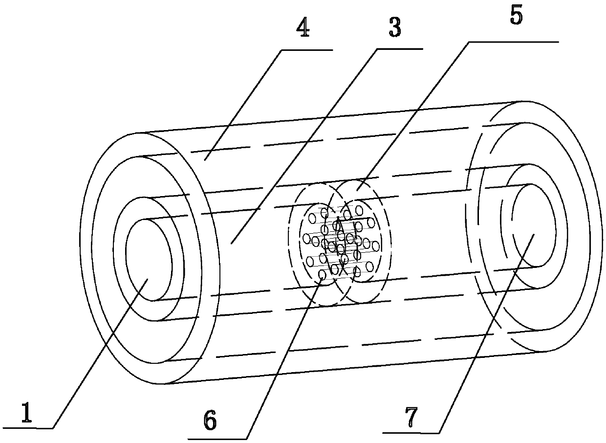
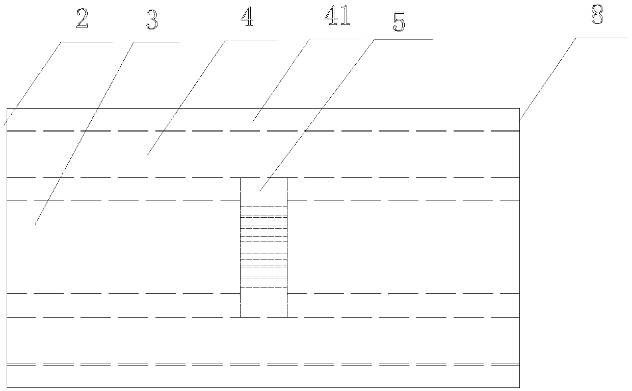
[0030] Such as figure 1 , figure 2 The shown seawater desalination device includes a main channel 3 and a buffer solution chamber 4 . The main channel 3 is a pipe-shaped cylindrical channel, and has a main channel inlet 1 and a main channel outlet 7 . The raw seawater solution to be desalinated is passed into the main channel 3 from the main channel inlet 1, and after desalination treatment, the fresh water solution flows out from the channel outlet 7 and leaves the desalination device.
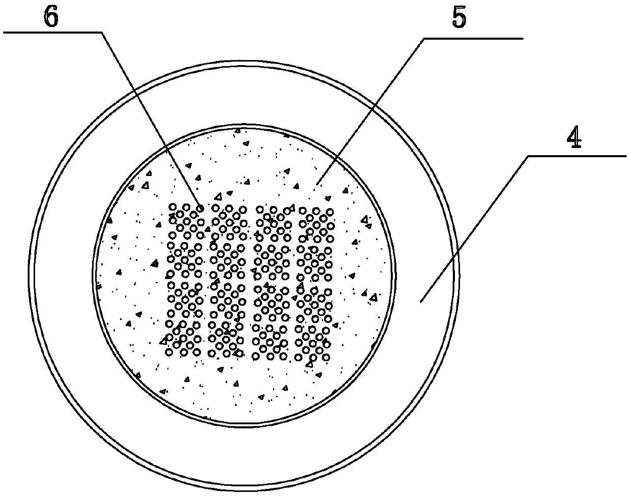
[0031] An ion-selective block 5 is arranged in the middle of the main channel 3 , and the ion-selective block 5 is a cylindrical shape conforming to the shape of the inner wall of the main channel 3 . Inside the ion-selective block 5, there are several parallel micro-channels 6 along the axial direction of the main channel 3. The opening direction of the micro-channels 6 is the same as that of the water flow. Preferably, it is 1 to 100 μm. The micron channels 6 are a...
Embodiment 2
[0038]A parallel seawater desalination device as described in Embodiment 1, the difference lies in that the cross-sectional shape of the buffer solution chamber 4 outside the main channel 3 is no longer required to be a ring structure. The buffer solution chamber 4 is provided with a buffer solution inlet 2 and a buffer solution chamber outlet 8, and the cation solution is led out of the buffer solution chamber 4 through the flowing buffer solution, thereby ensuring stable operation of the system.
[0039] At this time, the first electrode V is inserted at the main channel entrance 1 of the main channel 3 1 , whose potential is Φ 1 , the second electrode V is inserted at the main channel outlet 7 of the main channel 3 2 , whose potential is Φ 2 , where Φ is required 2 1 , the potential difference between the two ends of the main channel 3 is used to generate the first field intensity E covering the direction of the main channel 3 1 .
[0040] After the buffer solution cha...
PUM
 Abstract
Description
Claims
Application Information
 - R&D
- Intellectual Property
- Life Sciences
- Materials
- Tech Scout
- Unparalleled Data Quality
- Higher Quality Content
- 60% Fewer Hallucinations
Browse by: Latest US Patents, China's latest patents, Technical Efficacy Thesaurus, Application Domain, Technology Topic, Popular Technical Reports.
© 2025 PatSnap. All rights reserved.Legal|Privacy policy|Modern Slavery Act Transparency Statement|Sitemap|About US| Contact US: help@patsnap.com


