[0054] (4) Preparation of adsorbent: a. 10 parts by weight of eucalyptus bark, 5 parts of rice husk, 30 parts of bamboo, 3 parts of coconut husk, 10 parts of cassava hull, and 5 parts by weight of peanut husk are rolled into powder;
[0055] b. Then compound rice husk, cassava husk, peanut husk, coconut husk, bamboo, and eucalyptus bark into spherical porous particles from the inside to the outside.
[0056] Wastewater treatment: S1: Discharge the printing and dyeing wastewater to the adjustment tank to adjust the flow and quality of the wastewater, and add industrial sulfuric acid to the adjustment tank to adjust the pH of the wastewater to 6;
[0057] S2: Lead the wastewater in the regulating tank into the sedimentation tank, and add a sedimentation agent to the sedimentation tank for sedimentation;
[0058] S3: Simple filtration of wastewater in the sedimentation tank after sedimentation treatment;
[0059] S4: Mix the decolorizer and the microbial growth promoter and add them to the decolorization tank, and then introduce the filtered wastewater into the decolorization tank for decolorization;
[0060] S5: First pass the decolorized wastewater into ozone, and then add adsorbent for adsorption and catalysis;
[0061] S6: Treat the adsorbed wastewater through ultrafiltration;
[0062] Through the above six steps, wastewater that meets the discharge standards is obtained.
[0063] The decolorization step in S4 uses a printing and dyeing wastewater treatment device for treatment.
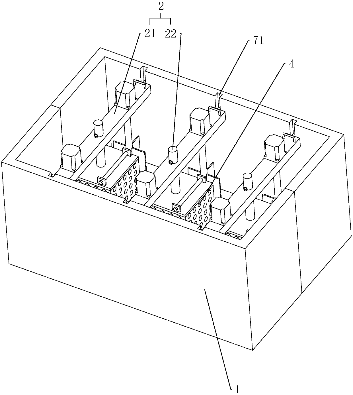
[0064] reference figure 1 , A printing and dyeing wastewater treatment device includes a regulating tank 1, a supporting component 2 is installed in the regulating tank 1, the supporting component 2 and the storage component 3 (see image 3 ) Is connected, the storage component 3 is connected to the shielding component 4.
[0065] Reference figure 1 with figure 2 , The support assembly 2 includes a mounting plate 21 and a connecting rod 22. Both ends of the mounting plate 21 are provided with sliding blocks 7, and a sliding groove 71 is provided on the side wall of the adjusting pool 1. The sliding groove 71 communicates with the upper end surface of the side wall of the adjusting pool 1. , The sliding block 7 is slidably installed in the sliding groove 71. The mounting plate 21 is provided with a fixing hole 211, and the mounting plate 21 is provided with a first clamping groove 212, and the first clamping groove 212 communicates with the fixing hole 211. The side wall of the fixing hole 211 is provided with a second clamping groove 213, and the second clamping groove 213 communicates with the first clamping groove 212. A first clamping block 221 is provided on the side wall of the connecting rod 22, and the first clamping block 221 is clamped with the second clamping slot 213.
[0066] A fixing block 5 is arranged in the first clamping groove 212, and the fixing block 5 is clamped and fixed to the first clamping groove 212, and an end of the fixing block 5 away from the bottom of the first clamping groove 212 is connected with a pull ring 51.
[0067] Reference figure 2 A rotating motor 6 is also installed on the mounting plate 21. A rotating rod 61 is provided on the side of the mounting plate 21 facing away from the rotating motor 6. The output shaft of the rotating motor 6 passes through the mounting plate 21 and is connected to the rotating rod 61 for rotation. A paddle 62 is connected to the end far away from the connection with the rotating motor 6. A pulling ring 8 is provided in the center of the symmetrical mounting plate 21 on the mounting plate 21.
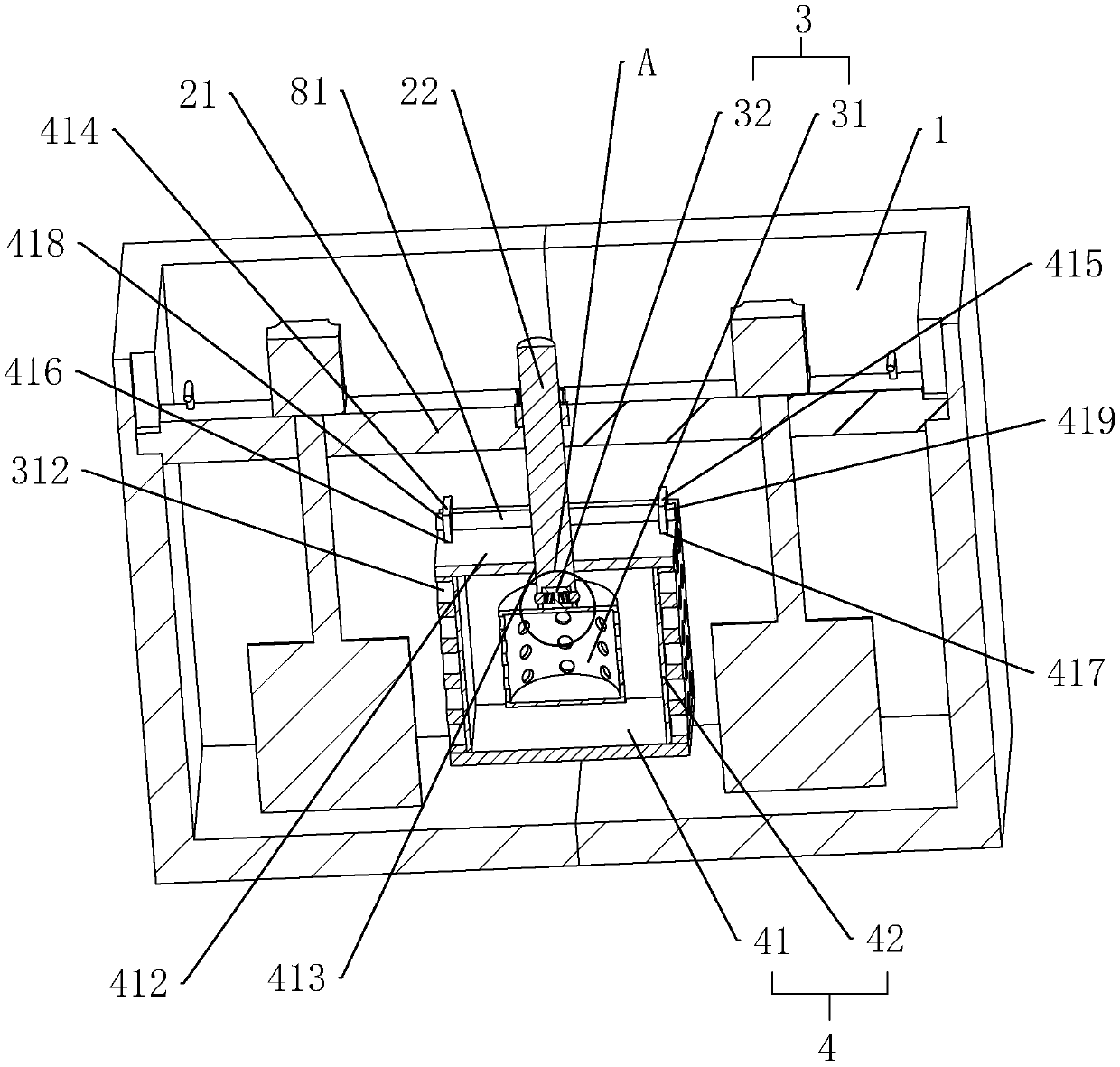
[0068] Reference image 3 with Figure 4 The storage assembly 3 includes a storage tank 31 and a connecting block 32. The connecting rod 22 is provided with a connecting groove 222 on one end away from the mounting plate 21. A locking hole 223 is provided on the side wall of the connecting groove 222. The connecting block 32 is connected to the storage One end of the material tank 31 is connected to the center of the end surface. The side wall of the connecting block 32 is provided with a telescopic groove 321. The telescopic groove 321 is provided with a spring 322. One end of the spring 322 is connected to the bottom of the telescopic groove 321, and the other end of the spring 322 is connected with A locking block 323 is connected. The storage tank 31 is clamped to the connecting groove 222 through the connecting block 32, and the locking block 323 is clamped to the locking hole 223 to be connected to the connecting rod 22. The side wall of the storage tank 31 is provided with evenly distributed permeable holes 312.
[0069] Reference image 3 , The outer side of the storage tank 31 is installed with a shielding assembly 4, the shielding assembly 4 includes a shielding box 41 and a filter screen 42, the shielding box 41 is close to the side opening of the connecting rod 22, the side wall of the opening end of the shielding box 41 is provided with a first convex Block 414 and the second bump 415, the peripheral side wall of the connecting plate 412 is provided with a first through hole 416 and a second through hole 417, the first bump 414 is inserted into the first through hole 416, and the second bump 415 Inserted with the second through hole 417, a first fixing hole 418 is formed on the end of the first bump 414 that passes through the first through hole 416, and a first fixing hole 418 is formed on the end of the second bump 415 that passes through the second through hole 417. The two fixing holes 419 are provided with a clamping rod 81 that is clamped to the first fixing hole 418 and the second fixing hole 419 so that the connecting plate 412 is fixed on the shielding box 41.
[0070] Reference image 3 A connecting hole 413 is opened in the center of the connecting plate 412, and the connecting rod 22 is slidably connected to the connecting hole 413, so that the shielding box 41 is connected to the connecting rod 22.
[0071] The peripheral side wall of the shielding box 41 is provided with parallel through holes, and a filter screen 42 is installed on the inner side of the peripheral side wall of the shielding box 41. The aperture of the filter screen 42 is smaller than the diameter of the water purifying substance.
[0072] The principle of implementation is:
[0073] Insert the end of the connecting rod 22 with the connecting groove 222 along the fixing hole 211 on the mounting plate 21, then insert the first clamping block 221 and the first clamping groove 212 on the connecting rod 22, and then rotate the connecting rod 22 The first clamping block 221 is rotated into the second clamping groove 213, the fixing block 5 is inserted along the first clamping groove 212, and the connecting rod 22 is fixed.
[0074] Then the connecting rod 22 passes through the connecting hole 413 on the connecting plate 412, and the connecting plate 412 is sleeved on the connecting rod 22.
[0075] Then the connecting block 32 of the storage tank 31 is inserted into the connecting groove 222 of the connecting rod 22. When inserting, the locking block 323 is pressed into the telescopic groove 321. When the insertion is completed, the locking block 323 corresponds to the locking hole 223. The pressure on the locking block 323 disappears, the locking block 323 is ejected from the telescopic groove 321, and the locking block 323 is inserted and fixed with the locking hole 223.
[0076] Then insert the first protrusion 414 and the second protrusion 415 on the open end of the shield box 41 into the first through hole 416 and the second through hole 417 on the connecting plate 412, and then insert the clamping rod 81 through the first through hole 417. A fixing hole 418 and a second fixing hole 419 connect the connecting plate 412 with the shield box 41.
[0077] The sliding block 7 of the mounting plate 21 is inserted into the sliding groove 71 of the adjusting tank 1 so that the sliding block 7 of the mounting plate 21 and the bottom of the sliding groove 71 conflict.
[0078] After the wastewater enters the regulating tank 1, the wastewater enters the shielding box 41 through the through holes on the shielding box 41 and the filter 42, and reacts with the water purifying agent in the storage tank 31, and the reaction product is in the shielding box 41. It settles inside and stays in the shielding box 41. The cleaned waste water flows out of the shielding box 41.