Heat regenerative system capable of improving unit peak load regulation capacity and dynamic calculation method of heat regenerative system heat storage tank steam temperature

A technology for a regenerative system and a heat storage tank is applied in the field of dynamic calculation of the steam temperature of the regenerative system and the heat storage tank of the regenerative system, and can solve the problems of poor peak shaving capability and flexibility of thermal power units.

Inactive Publication Date: 2019-03-29
NORTHEAST DIANLI UNIVERSITY +2
View PDF6 Cites 12 Cited by
  • Summary
  • Abstract
  • Description
  • Claims
  • Application Information

AI Technical Summary

Problems solved by technology

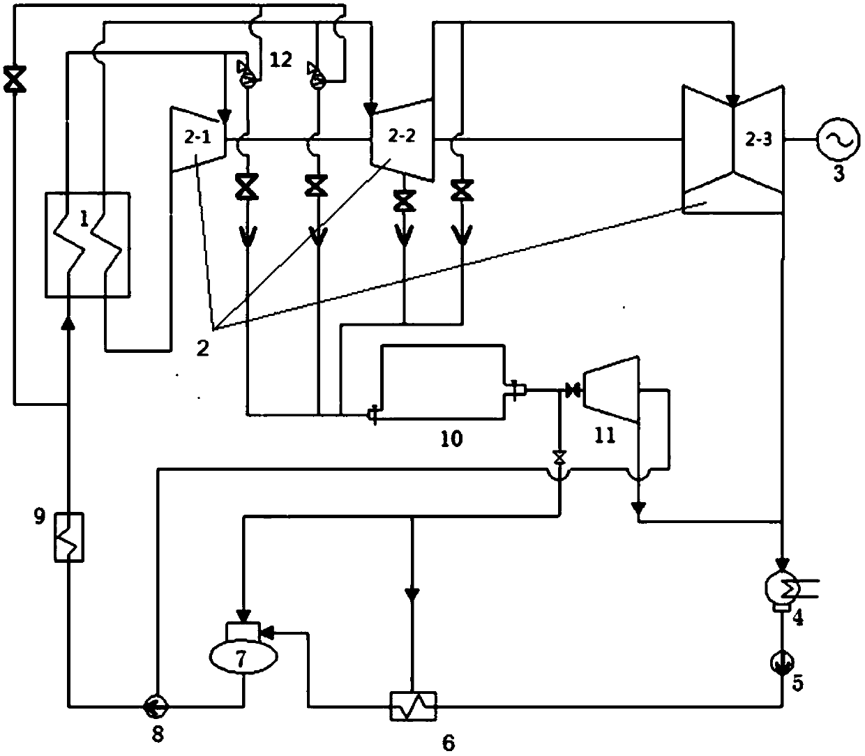
[0007] Aiming at the current problem of poor peak-shaving ability and flexibility of thermal power units, the purpose of the present invention is to provide a heat recovery system that can improve the peak-shaving ability of the unit; Dynamic Calculation Method of Steam Temperature Variation in Heat Storage Tank

Method used


Image

  • Heat regenerative system capable of improving unit peak load regulation capacity and dynamic calculation method of heat regenerative system heat storage tank steam temperature
  • Heat regenerative system capable of improving unit peak load regulation capacity and dynamic calculation method of heat regenerative system heat storage tank steam temperature
  • Heat regenerative system capable of improving unit peak load regulation capacity and dynamic calculation method of heat regenerative system heat storage tank steam temperature

Examples


example

[0241] Transform the formula (29) to get the following formula

[0242]

[0243] In the formula: dT is the change of steam temperature in the heat storage tank, ℃; dτ is the micro-increment of time, s; Δτ is the time interval, s; T 0 is the initial temperature of the heat storage tank, °C; T 1 is the temperature after the Δτ time interval, °C. q m,in is the mass flow rate of steam flowing into the heat storage tank, kg / s; m 1 for T 1 Steam mass of heat storage tank at any time, kg; h 0 is the steam enthalpy flowing into the heat storage tank, kJ / kg; h 2 is the exhaust enthalpy of small steam turbine, kJ / kg; c v Specific heat capacity for constant volume of steam in heat storage tank, kJ / (kg °C); c P is the specific heat capacity of steam at constant pressure in the heat storage tank, kJ / (kg °C), and γ is c P with c v Ratio.

[0244] Further derivation can be obtained:

[0245]

[0246] In the formula: T 0 is the initial temperature of the heat storage tank, ℃...


PUM


Abstract

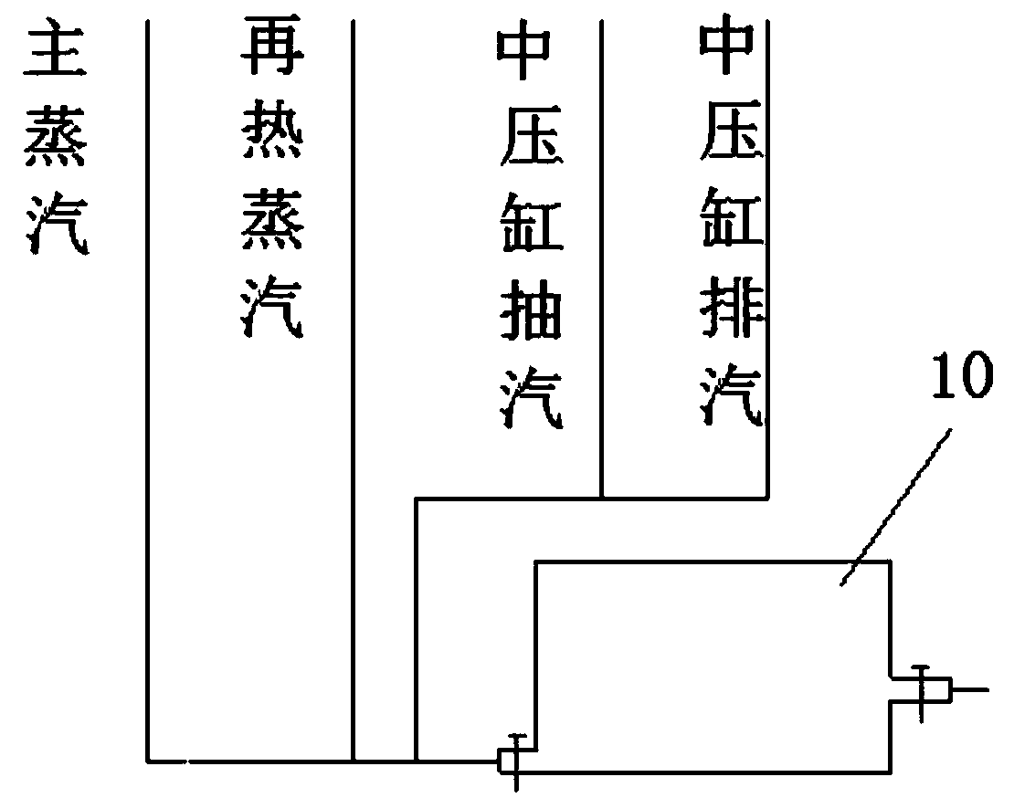
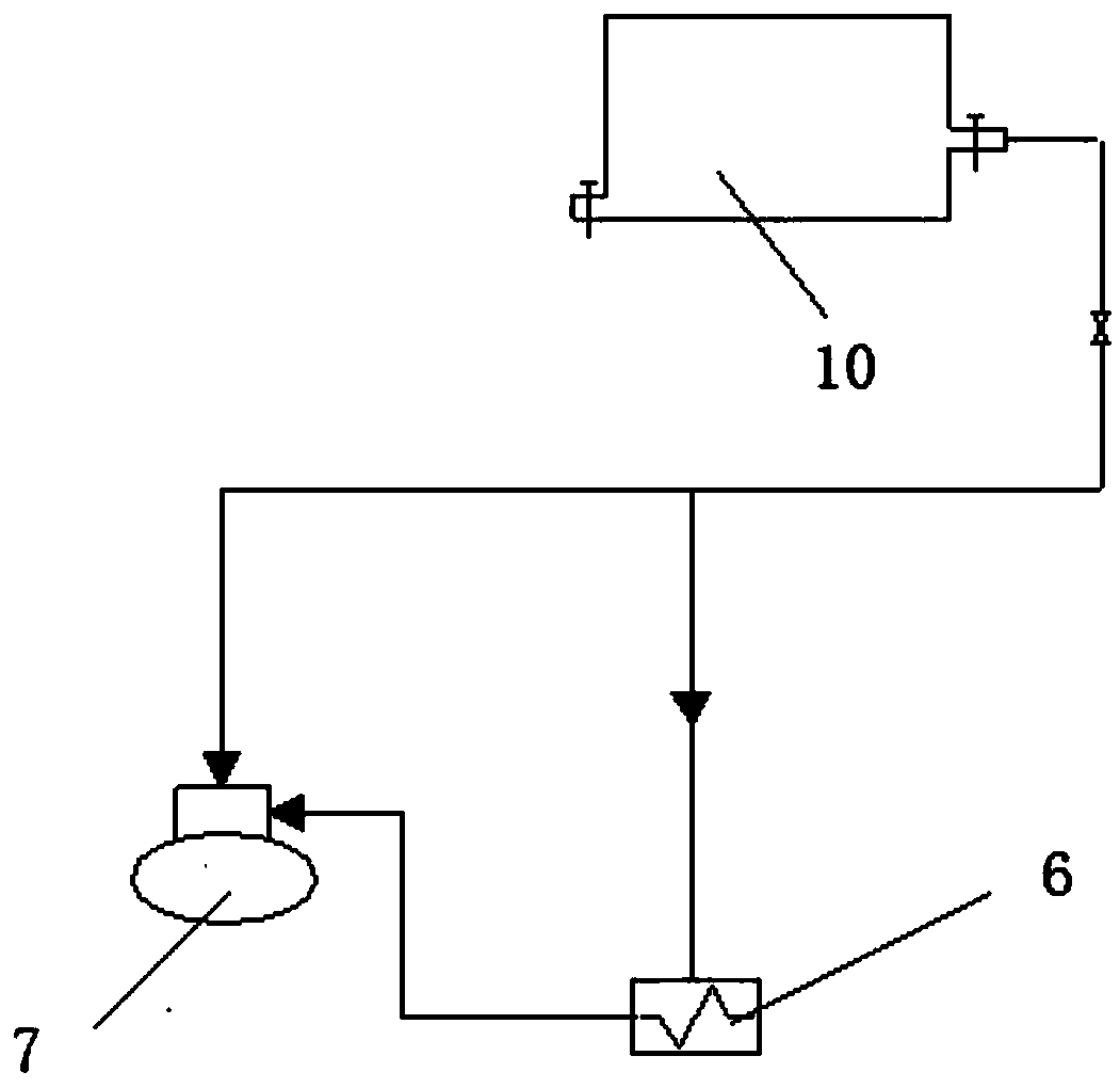
The invention provides a heat regenerative system capable of improving the unit peak load regulation capacity. The heat regenerative system comprises a power station boiler, a steam turbine, an electric generator, a steam condenser, a condensate pump, a low pressure heater, a deaerator, a water feed pump, a high pressure heater, a small steam turbine and a temperature and pressure reducer. The heat regenerative system is characterized by further comprising a heat storage tank, and steam is supplied to the heat regenerative system and the small steam turbine through the heat storage tank. Whenthe unit electric generation load is reduced, the heat storage tank extracts rich high-temperature steam from the steam turbine, and heat is directly stored in the heat storage tank in a steam mode. When the unit load is high, boiler feed water is increased, steam consumption of the heat regenerative system and the small steam turbine is increased, at the movement, steam stored in the heat storagetank can be released to be provided for the heat regenerative system and the small turbine, steam extracted from the unit can be reduced, unit force discharge is increased, and the effect load leveling is achieved. The invention further provides a dynamic calculation method of heat storage tank temperature changes.

Description

technical field [0001] The invention relates to the field of thermal equipment performance state monitoring and diagnosis during the peak regulation process of a coal-fired power unit, and is a dynamic calculation method for a heat recovery system and a heat storage tank steam temperature of the heat recovery system that can improve the peak regulation capability of the unit. Background technique [0002] In recent years, with the deepening of national energy conservation and emission reduction policies, clean energy has developed rapidly. However, with the rapid development of wind power, it is also facing serious problems of wind curtailment. Due to the regional characteristics of wind power, 80% of my country's wind energy resources are concentrated in the "three north" regions, namely the northeast, north and northwest regions; the energy supply and energy demand in the "three north" regions are reversely distributed. The problem of curtailment of wind power is becoming...

Claims


Application Information

Patent Timeline
Patent Type & Authority Applications(China)
IPC IPC(8): F01K3/14F01K11/02F01D15/10F22D1/50G06F17/50
CPCF01D15/10F01K3/14F01K11/02F22D1/50G06F30/20G06F2119/08
Inventor 曹丽华司和勇董恩伏胡鹏飞马汀山葛维春李树阳杨荣祖王艳红姜铁骝罗桓桓周桂平戴黎
Owner NORTHEAST DIANLI UNIVERSITY
Why Eureka
Try Eureka