A Double-Telecentric Optical System with Two Optical Paths

An optical system, bi-telecentric technology, applied in optics, optical components, instruments, etc., can solve the problem of inability to obtain SMT package circuit parameters and size information, and achieve outstanding substantive features, high resolution, and high material repetition rate. Effect

Active Publication Date: 2021-03-16
UNIV OF SHANGHAI FOR SCI & TECH
View PDF7 Cites 0 Cited by
  • Summary
  • Abstract
  • Description
  • Claims
  • Application Information

AI Technical Summary

Problems solved by technology

The traditional AOI inspection system is limited to the two-dimensional inspection of the surface of the PCB, and cannot obtain the parameters and dimensions of the SMT package circuit in the longitudinal and depth directions. However, the three-dimensional imaging technology based on structured light can solve this problem.

Method used


Image

  • A Double-Telecentric Optical System with Two Optical Paths
  • A Double-Telecentric Optical System with Two Optical Paths
  • A Double-Telecentric Optical System with Two Optical Paths

Examples


Embodiment 1

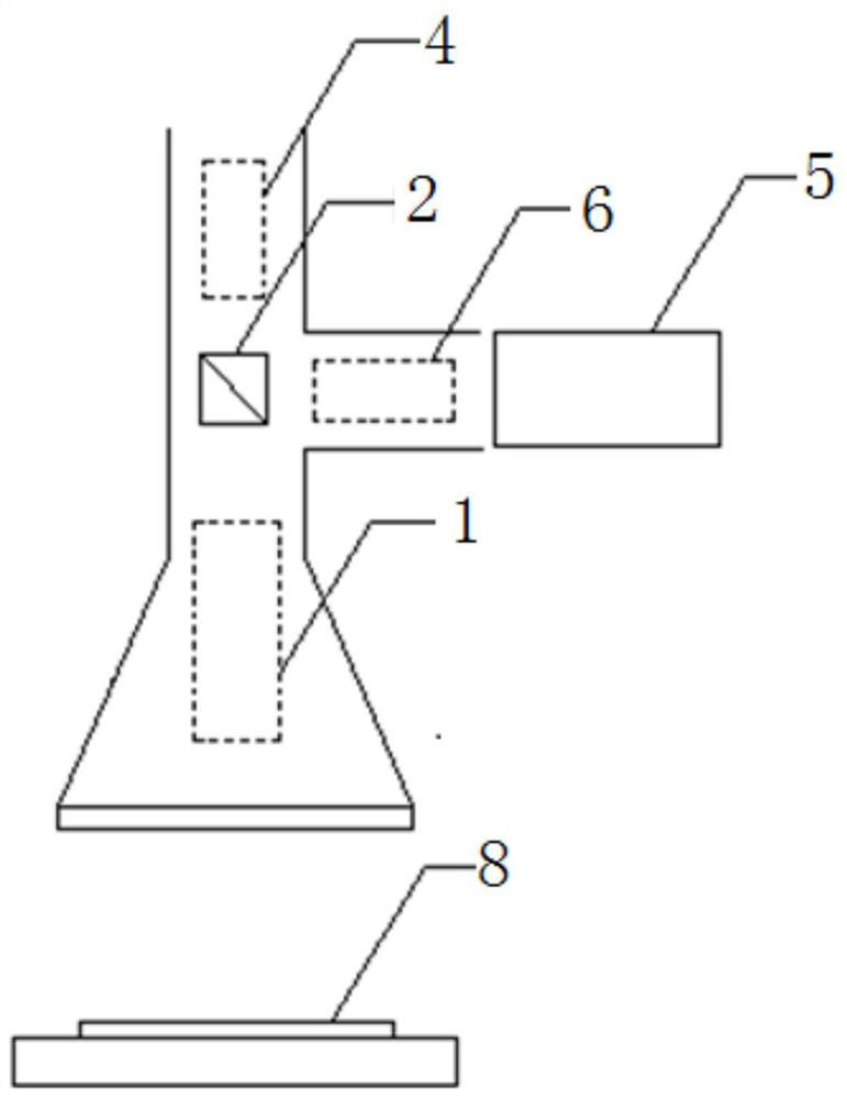
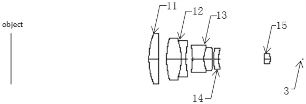
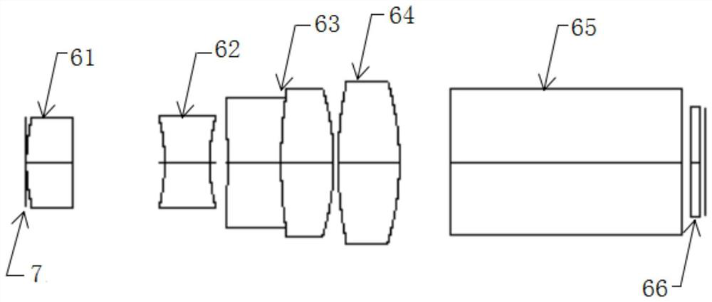
[0029] combine Figure 1 to Figure 10 As shown, this embodiment provides a double-optical-path double-telecentric optical system, the double-light-path double-telecentric optical system includes a projection system and an imaging system, and the imaging system is sequentially provided with a common optical path objective lens from the object plane to the image plane Group 1, dichroic prism 2, diaphragm one 3 and imaging objective lens group 4, the projection system includes illumination system 5, projection objective lens group 6, diaphragm two 7, dichroic prism 2 and common optical path objective lens from the illumination system to the object plane Group 1, the imaging system and the projection system share the common optical path objective lens group 1 and the dichroic prism 2, and the projection system projects the modulated fringe light generated by the illumination system 5 onto the object surface, the The imaging system images the fringe light information reflected by t...

Embodiment 2

[0039] The dual optical path bi-telecentric optical system provided in this embodiment is only different from that of Embodiment 1 in that: the refractive power of the first lens 11 is 0.0092, and the refractive power of the second lens 12 is 0.0027. The third lens 13 has a refractive power of -0.0140, the fourth lens 14 has a refractive power of -0.0046, the fifth lens 15 has a refractive power of 0.0062; the sixth lens 61 has a refractive power of 0.0330, The refraction power of the seventh lens 62 is -0.0811, the refraction power of the eighth lens 63 is 0.0187, the refraction power of the ninth lens 64 is 0.0328; the refraction power of the twelfth lens 41 is -0.0022 , the focal power of the thirteenth lens 42 is 0.0079, the focal power of the fourteenth lens 43 is -0.0004, the focal power of the fifteenth lens 44 is 0.0055, and the focal power of the sixteenth lens 46 is The degree is 0.0048.

[0040] To sum up, it can be seen that the double-optical path double-telecent...


PUM


Abstract

The invention discloses a double-optical-path double-telecentric optical system. The optical system comprises a projection system and an imaging system; the imaging system is sequentially provided with a common-optical-path objective lens set, a beam splitter prism, a diaphragm I and an imaging objective lens set from an object surface to an image surface; the projection system comprises a lighting system, a projection objective lens set, a diaphragm II, a beam splitter prism and a common-optical-path objective lens set from a lighting system to the object surface; the projection system projects modulated stripe light generated by the lighting system onto the object surface; and the imaging system is used for imaging stripe light information reflected by the object surface on the image surface. The optical system is high in integration level, high in precision, high in resolution, high in telecentricity and small in distortion, can effectively improve the imaging quality, and can be applied to the field of high-precision detection of optical lenses; and in addition, materials used by the lenses are relatively high in repetition rate, so that the processing is facilitated, and the cost is reduced.

Description

technical field [0001] The present invention relates to an optical system, in particular to a high-precision, high-telecentric double-optical path double-telecentric optical system, which is especially suitable for machine vision inspection equipment for PCB board products based on SMT surface mount technology , belonging to the field of optical imaging technology. Background technique [0002] In large-scale industrial production, online inspection based on machine vision can greatly improve production efficiency and industrial automation level. As an important part of the detection system, the imaging lens has higher and higher design requirements. With the development of SMT packaging technology, the PCB gradually tends to be denser and more refined, and the requirements for the production quality of SMT packaged circuit boards are increased, which makes it particularly important to detect and detect defects in SMT packaged circuit boards in time. The traditional AOI in...

Claims


Application Information

Patent Timeline
Patent Type & Authority Patents(China)
IPC IPC(8): G02B27/00G02B13/00G02B13/22G03B21/14
CPCG02B13/0015G02B13/006G02B13/22G02B27/0025G03B21/142
Inventor 韦晓孝李雪宸万新军吕元
Owner UNIV OF SHANGHAI FOR SCI & TECH
Why Eureka
Try Eureka