
An optical fiber libs detection device and method used in the main pipeline of a nuclear power plant

A detection device and a technology for nuclear power plants, applied in the field of laser diagnosis, can solve the problems of adverse effects on the system, difficult to achieve long-distance online measurement, inability to evaluate and predict life, and achieve the effects of rapid quantitative analysis, high efficiency, and safe and reliable operation.

Active Publication Date: 2020-03-17
XI AN JIAOTONG UNIV +1
View PDF7 Cites 0 Cited by
  • Summary
  • Abstract
  • Description
  • Claims
  • Application Information

AI Technical Summary

Problems solved by technology

Due to the harsh operating environment of nuclear power plants such as high radioactivity, high temperature, and high pressure, conventional detection methods, such as X-ray photography technology, ultrasonic technology, and eddy current technology, are difficult to achieve long-distance online measurement
The newly developed remote online detection technologies such as acoustic emission technology and electrochemical technology also have their own limitations: for example, acoustic emission technology can only detect the pressure wave signal emitted by the material being damaged, and cannot evaluate and predict its life ; Electrochemical technology needs to add small-amplitude electrical signal disturbance to the nuclear power system, which may cause adverse effects on the system
At present, my country has not yet established a laser-induced spectral database for nuclear power plant steel and quantitative measurement methods for its elemental components.

Method used


Image

  • An optical fiber libs detection device and method used in the main pipeline of a nuclear power plant
  • An optical fiber libs detection device and method used in the main pipeline of a nuclear power plant
  • An optical fiber libs detection device and method used in the main pipeline of a nuclear power plant

Examples


Embodiment Construction

[0040] In order to enable those skilled in the art to better understand the solutions of the present invention, the following will clearly and completely describe the technical solutions in the embodiments of the present invention in conjunction with the drawings in the embodiments of the present invention. Obviously, the described embodiments are only It is an embodiment of a part of the present invention, but not all embodiments. Based on the embodiments of the present invention, all other embodiments obtained by persons of ordinary skill in the art without making creative efforts shall fall within the protection scope of the present invention.

[0041] It should be noted that the terms "first" and "second" in the description and claims of the present invention and the above drawings are used to distinguish similar objects, but not necessarily used to describe a specific sequence or sequence. It is to be understood that the data so used are interchangeable under appropriate ...


PUM

PropertyMeasurementUnit
diameteraaaaaaaaaa
diameteraaaaaaaaaa
diameteraaaaaaaaaa

Abstract

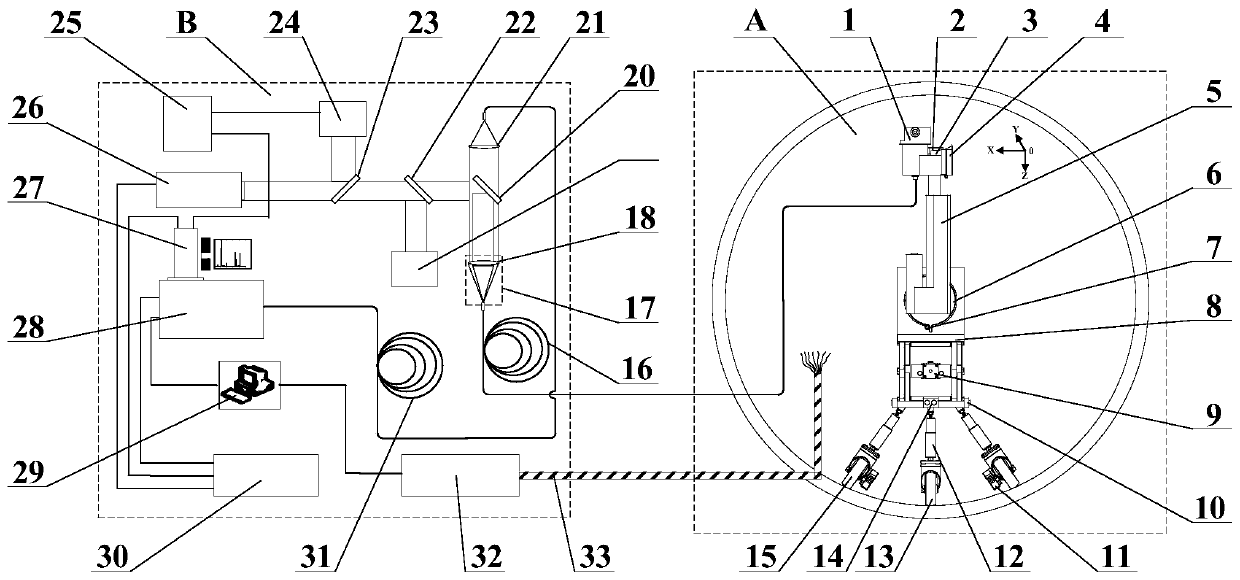
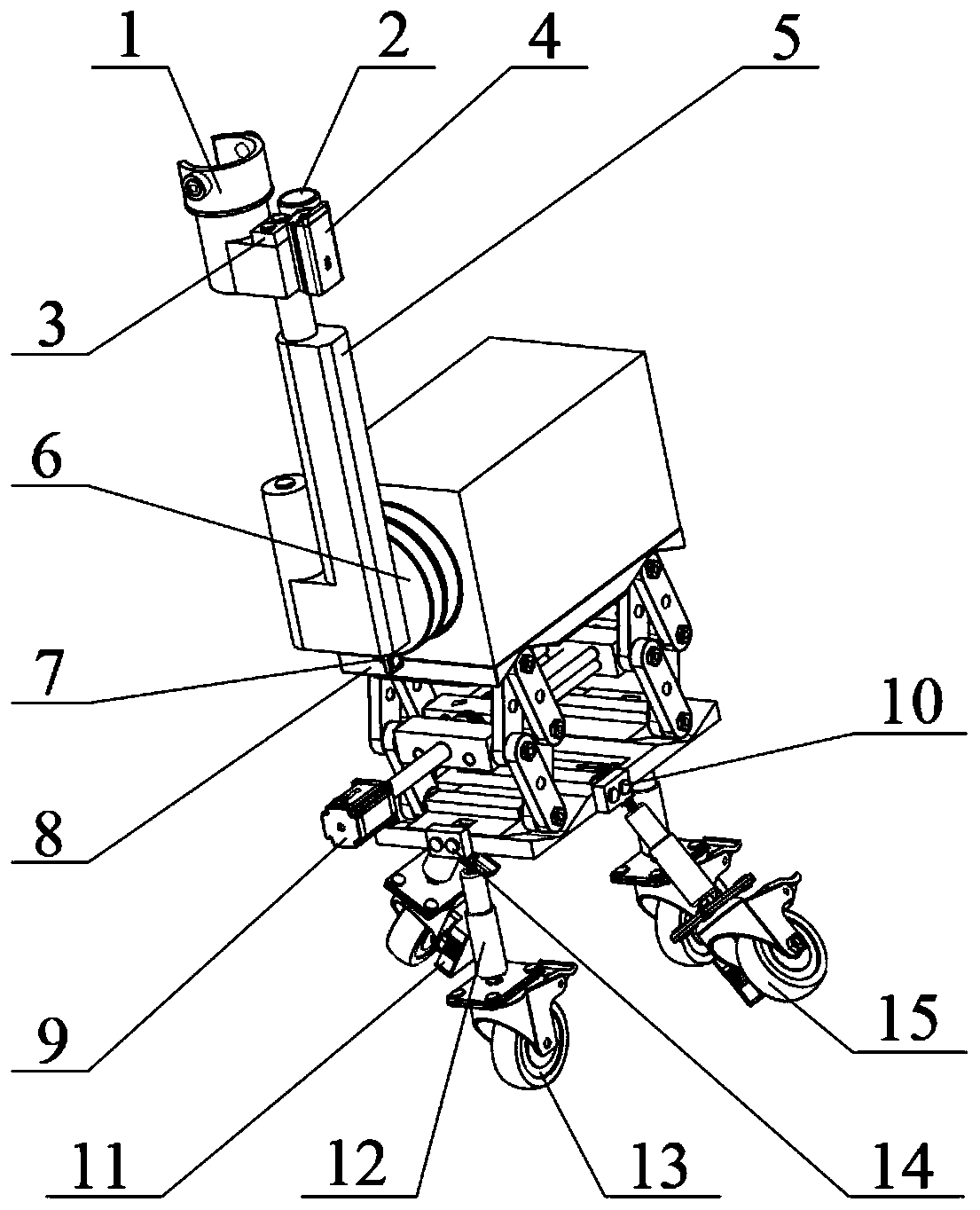
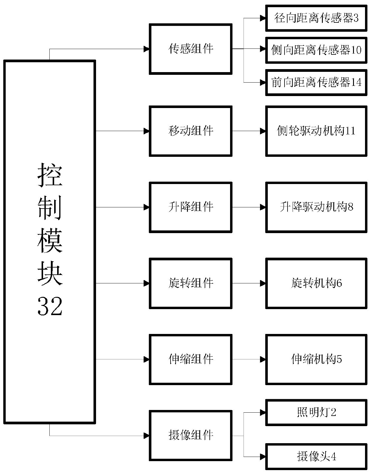
The invention discloses an optical fiber LIBS detection device and method used in the main pipeline of a nuclear power plant, comprising two parts: an optical fiber LIBS detector and a main control detection system; the main control detection system is installed in the main control room of the nuclear power plant, and the optical fiber LIBS detector enters the pipeline The detection operation is carried out inside, and the two are connected by the transmission optical fiber and the control signal line. The main control detection system of the present invention and the optical fiber LIBS detector are connected to the control signal line through a high-temperature-resistant high-power transmission optical fiber, and the remote on-line detection of the designated area of ​​the inner wall of the main pipeline of the nuclear power plant can be realized in the main control room of the nuclear power plant. The pipeline is pretreated, and the inner wall of the pipeline is slightly damaged or even non-destructive, which can realize rapid quantitative analysis of various elements at the same time, and the operation of the entire detection process is safe, reliable, and efficient.

Description

【Technical field】 [0001] The invention belongs to the technical field of laser diagnosis, and relates to an optical fiber LIBS detection device and method used in a main pipeline of a nuclear power plant. 【Background technique】 [0002] The status monitoring, maintenance and evaluation technology of the key structure of the reactor is an important support for the safety and economy of nuclear power. Conduct in-service and pre-service non-destructive testing. Due to the harsh operating environment of nuclear power plants such as high radioactivity, high temperature, and high pressure, conventional detection methods, such as X-ray photography technology, ultrasonic technology, and eddy current technology, are difficult to achieve long-distance online measurement. The newly developed remote online detection technologies such as acoustic emission technology and electrochemical technology also have their own limitations: for example, acoustic emission technology can only detect ...

Claims


Application Information

Patent Timeline
Patent Type & Authority Patents(China)
IPC IPC(8): G01N21/63G01J3/443G01J3/02G21C17/017
CPCG21C17/017G01J3/0202G01J3/0218G01J3/027G01J3/443G01N21/63G01J2003/283Y02E30/30G01S15/08G01S15/88G01N21/718G01N2201/08G01N21/954G01N2021/9542G01N21/6402G01N2201/021G01N2201/06113G01N2201/0636
Inventor 吴坚张智邱岩刘韬薛飞李兴文
Owner XI AN JIAOTONG UNIV
Learn More