Millimeter wave broadband circularly polarized antenna based on substrate-integrated waveguide horn

A substrate-integrated waveguide and circularly polarized antenna technology, applied in the field of mobile satellite communications and 5G wireless communication systems, and millimeter-wave broadband circularly polarized antennas, can solve unfavorable low cost and large-scale processing, and unfavorable broadband circularly polarized radiation , narrow circular polarization working bandwidth and other issues, to achieve stable broadband circular polarization radiation, realize broadband circular polarization radiation, and easy processing

Active Publication Date: 2019-04-02
XIDIAN UNIV
View PDF7 Cites 5 Cited by
  • Summary
  • Abstract
  • Description
  • Claims
  • Application Information

AI Technical Summary

Problems solved by technology

However, the traditional integrated waveguide horn antenna has a narrow matching bandwidth and is linearly polarized radiation
Gradient or loading structures can be introduced to broaden its matching bandwidth, but these structures are often more complex, which is not conducive to low cost and mass processing, and is also not conducive to the realization of broadband circularly polarized radiation.
The circularly polarized radiation of the substrate integrated waveguide antenna can be realized by array, multi-feed and multi-layer thick dielectric plate structure, but the circularly polarized working bandwidth is often narrow, the structure is more complicated, and most of them are edge-radiated. Antenna, which limits its application in broadband wireless communication

Method used


Image

  • Millimeter wave broadband circularly polarized antenna based on substrate-integrated waveguide horn
  • Millimeter wave broadband circularly polarized antenna based on substrate-integrated waveguide horn
  • Millimeter wave broadband circularly polarized antenna based on substrate-integrated waveguide horn

Examples


Embodiment Construction

[0030] The structure and effects of the present invention will be further described in detail below in conjunction with the accompanying drawings and specific embodiments.

[0031] This example takes an antenna working in the 22-31GHz frequency band, that is, the 5G millimeter wave frequency band, as an example

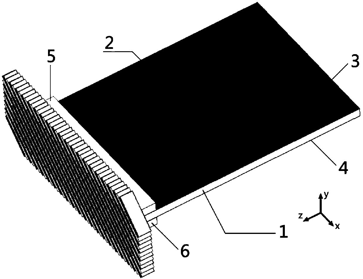
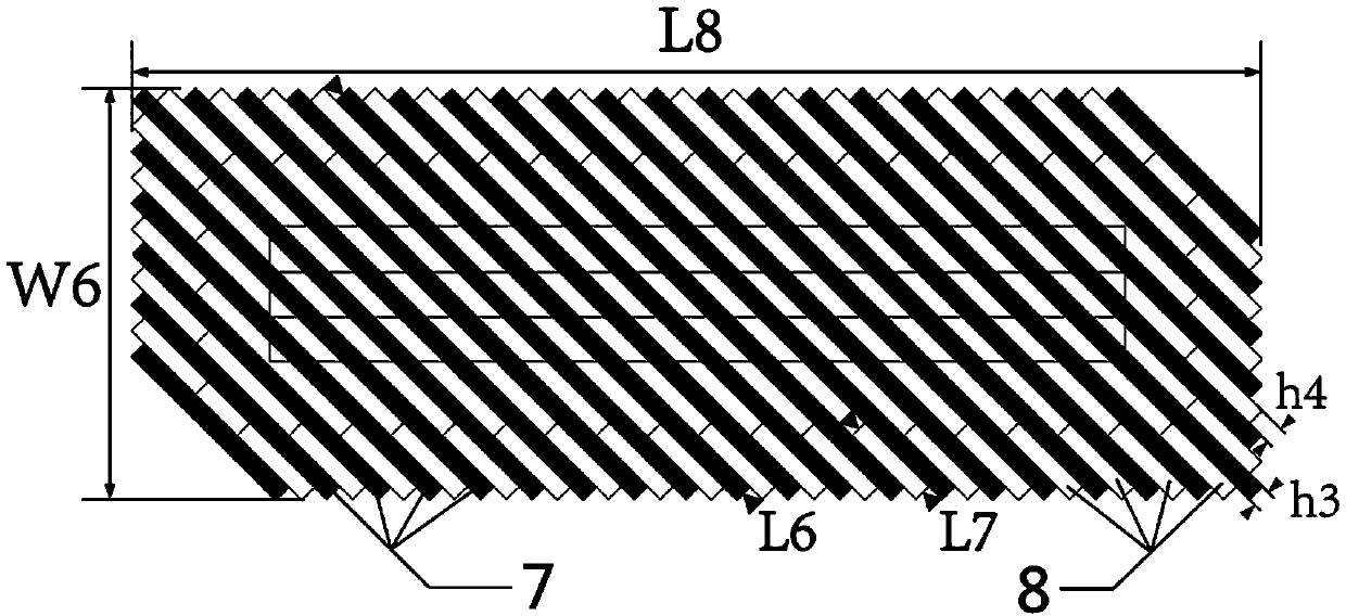
[0032] refer to figure 1 , this example includes a dielectric plate 1 , a metallized through-hole array 2 , an upper metal layer 3 , a lower metal layer 4 , an upper dielectric block 5 , a lower dielectric block 6 , a polarization converter 7 and a polarization converter support structure 8 . in:

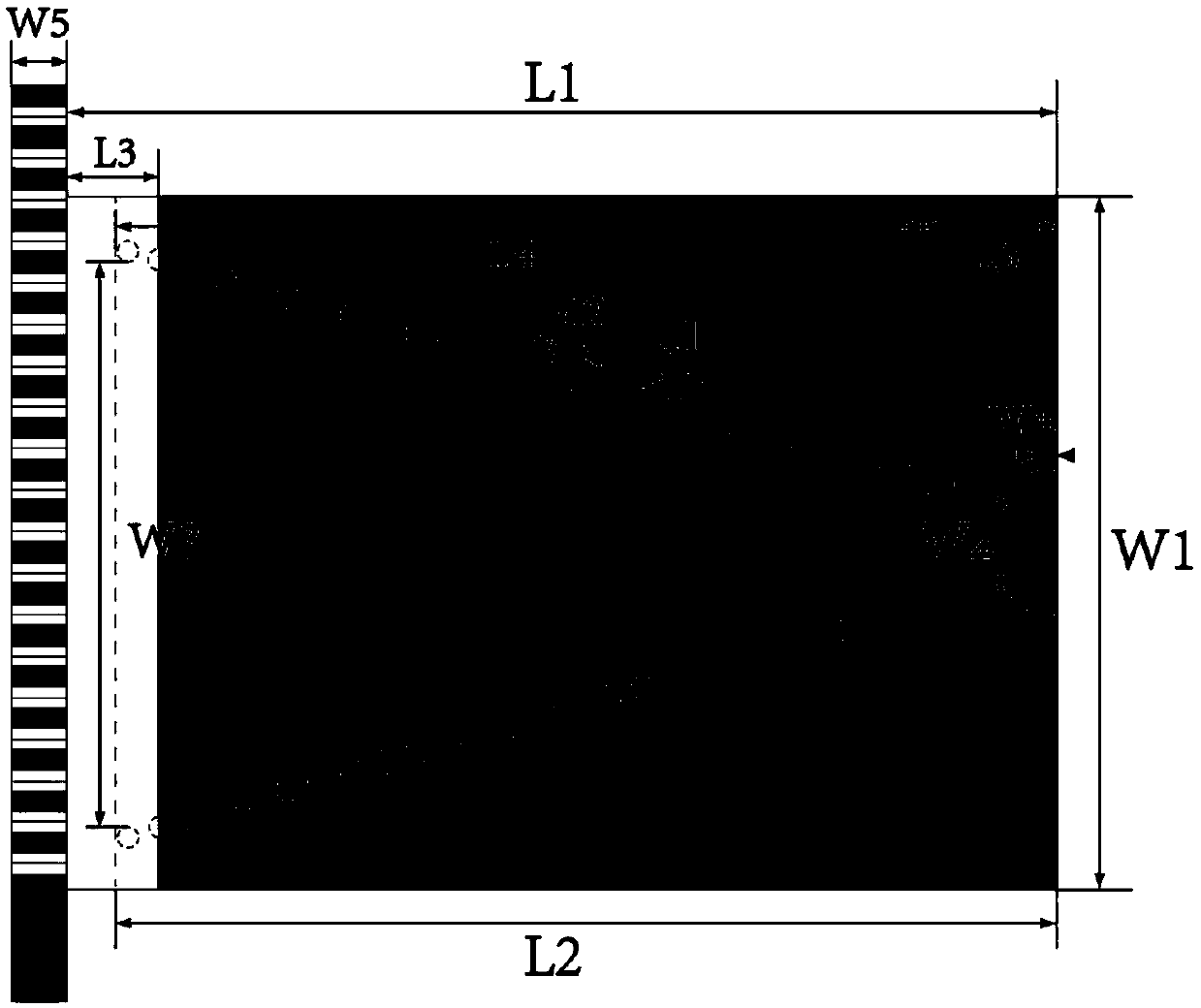
[0033] The upper metal layer 3 and the lower metal layer 4 are respectively arranged on the upper and lower surfaces of the dielectric plate 1 and have the same structure and shape. In this example, but not limited to, the shape of the upper metal layer 3 and the lower metal layer 4 is a rectangle. The upper metal layer 3 and the lower metal layer 4 coincide with the die...


PUM


Abstract

The invention discloses a millimeter wave broadband circular polarized antenna based on a substrate-integrated waveguide horn, and aims to solve the problem of difficulty in realizing broadband circularly polarization in an existing substrate-integrated waveguide horn antenna. The millimeter wave broadband circularly polarized antenna comprises a dielectric plate (1), an upper metal layer (3), a lower metal layer (4), an upper dielectric block (5), a lower dielectric block (6), a polarized converter (7) and a polarized converter support structure (8), wherein the upper metal layer and the lower metal layer are located on an upper surface and a lower surface of the dielectric plate respectively; the dielectric plate is provided with a metallized through hole array (2) with gradually-varyinggaps in order to construct a feed-horn structure; the upper dielectric block and the lower dielectric block are arranged above and below a horn radiation aperture respectively to realize broadband impedance matching; and the polarized converter and the support structure thereof are located at the edge of the horn radiation aperture to realize stable broadband circularly polarized radiation. The millimeter wave broadband circular polarized antenna has the advantage of circularly polarized radiation with stable broadband under the millimeter wave frequency, and is suitable for a broadband millimeter wave wireless communication system.

Description

technical field [0001] The invention belongs to the technical field of antennas, in particular to a millimeter-wave broadband circularly polarized antenna, which can be applied to mobile satellite communication and 5G wireless communication systems. Background technique [0002] Circularly polarized antennas are widely used in applications such as satellite communications, remote sensing, and deep space exploration because they can avoid multipath effects, polarization mismatches, and Faraday rotation effects. The broadband antenna has been widely researched and applied because it can reduce system complexity and improve communication capacity. However, traditional broadband circularly polarized antennas often have large dimensions and non-planar structures, making it difficult to integrate with planar circuits; this limits their application in many highly integrated wireless communication systems. In order to solve this problem, substrate integrated waveguide technology is...

Claims


Application Information

Patent Timeline
Patent Type & Authority Applications(China)
IPC IPC(8): H01Q13/02H01Q1/50H01Q1/38H01Q15/24
CPCH01Q1/38H01Q1/50H01Q13/0241H01Q15/244
Inventor 焦永昌张依轩张立翁子彬张炫
Owner XIDIAN UNIV
Why Eureka
Try Eureka