Two-degree-of-freedom heterodyne optical grating interference measurement method and system with high tolerance

A technology of grating interference and measurement system, which is applied in the direction of interferometer, measuring device, optics, etc., can solve the problems of anti-aliasing, high-magnification optical subdivision and high angle tolerance, short distance between laser light source and optical mirror group, etc. Installation and alignment requirements are high, so as to improve measurement resolution, ensure effective coupling, and improve energy utilization.

Active Publication Date: 2019-04-05
HARBIN INST OF TECH
View PDF13 Cites 12 Cited by
  • Summary
  • Abstract
  • Description
  • Claims
  • Application Information

AI Technical Summary

Problems solved by technology

Tsinghua University Chinese patent CN106289068A (disclosure date January 4, 2017) discloses a displacement measurement method of a two-degree-of-freedom heterodyne grating interferometer, which uses separately modulated dual-frequency laser light sources and a Littrow optical structure. The measurement of the horizontal displacement and vertical displacement of the grating has the characteristics of anti-optical aliasing and miniaturization, but the differential Littrow structure in this scheme can only realize the optical subdivision of the horizontal displacement of the grating
In addition, in this structure, the distance between the laser light source and the optical mirror group is relatively close, and the heating of the laser light source will cause a certain thermal drift; and the beam is transmitted in space, which requires high installation and alignment
The above research shows that the existing technology has not yet taken into account the characteristics of anti-aliasing, high-magnification optical subdivision and high angle tolerance, and further research is still needed to better meet the increasing demand for measurement systems in application environments such as lithography machines

Method used


Image

  • Two-degree-of-freedom heterodyne optical grating interference measurement method and system with high tolerance
  • Two-degree-of-freedom heterodyne optical grating interference measurement method and system with high tolerance
  • Two-degree-of-freedom heterodyne optical grating interference measurement method and system with high tolerance

Examples


Embodiment Construction

[0017] The specific embodiments of the present invention will be further described in detail below in conjunction with the accompanying drawings.

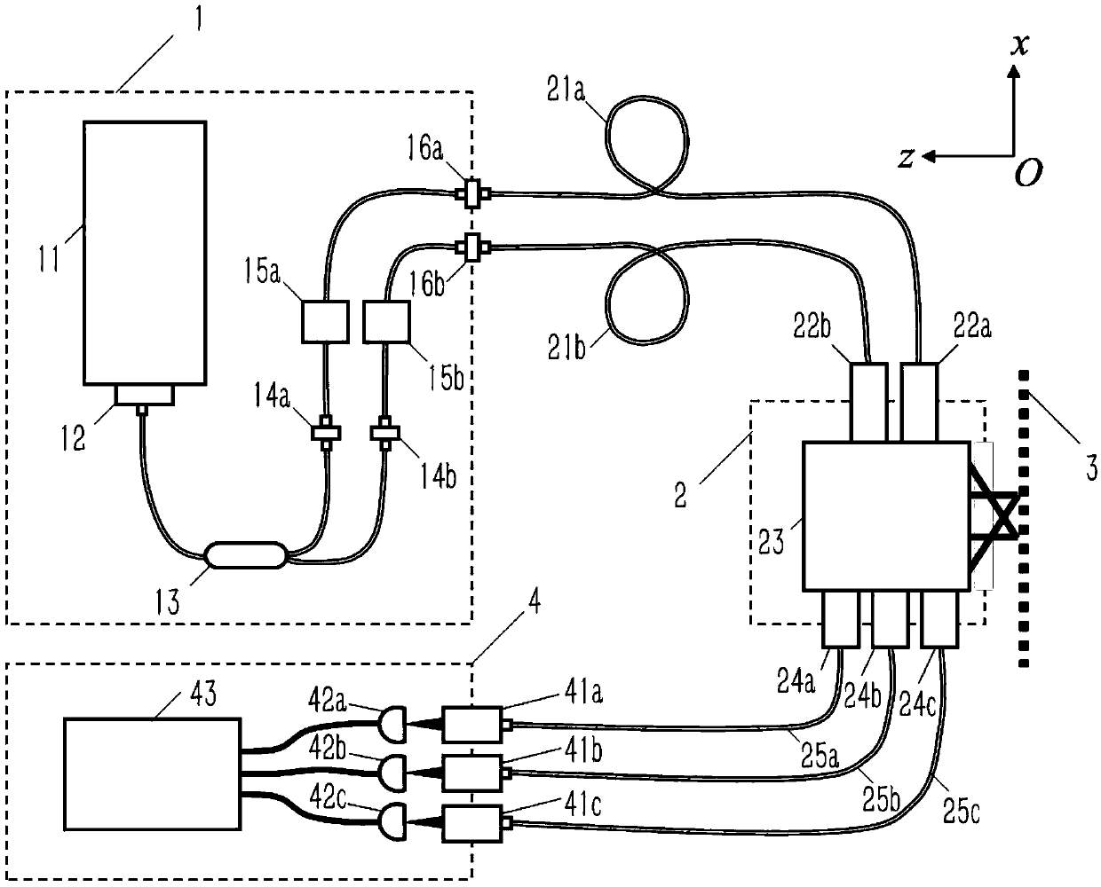
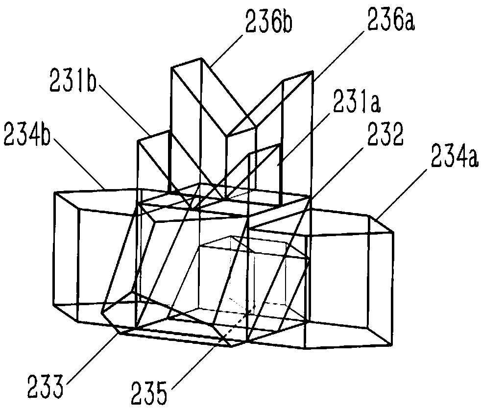
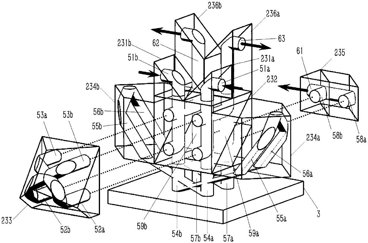
[0018] A high-tolerance two-degree-of-freedom heterodyne grating interferometry method. The heterodyne laser outputs two laser beams simultaneously, wherein the first laser beam is at the first frequency, and the second laser beam is at the second frequency, separated in space. Transmitted to the first beam splitting surface to obtain the corresponding reference beam and measurement beam, wherein the two reference beams pass through the retroreflector structure to form the first reference beam and the second reference beam, and enter the third beam splitting surface; the two measurement beams are perpendicular to the measured grating , through the secondary diffraction structure formed by the grating-retroreflector, the corresponding first measurement beam and the second measurement beam are obtained, and are divided into two parts ...


PUM


Abstract

The invention relates to a two-degree-of-freedom heterodyne optical grating interference measurement method and system with high tolerance. The system comprises a separate modulating heterodyne lasermodule, an optical grating interference mirror group and a photoelectric detection and signal processing unit; the separate modulating heterodyne laser module simultaneously outputs two lasers with different frequencies to parallelly enter into a first optical splitting surface to optical split at the same time, part of the incident lasers produce a reference beam to a reflector to enter into a third optical splitting surface, the other part of the lasers pass through a measured grating-backward reflector and form a secondary diffraction structure to obtain two measured beams, and the lasers enter into the second optical splitting surface is divided into two parts; and one part optically combines to form a first interference beam, the other part enters the third optical splitting surface and optically combines with the corresponding reference beam to form a second and third interference beams, and optical beat frequency signals of the three interference beams calculates horizontal andvertical displacement information of optical grating by photoelectric detection and signal processing. The method and system improve the optical fine fraction, and meanwhile, improve the angle tolerance of optical grating deflection.

Description

technical field [0001] The invention relates to a grating measurement method and system, in particular to a high-tolerance two-degree-of-freedom heterodyne grating interferometry method and system. Background technique [0002] Lithography machine is the core equipment in the field of integrated circuit manufacturing, which is used to align and expose wafers. Among them, the ultra-precision workpiece table is one of the core subsystems of the lithography machine, which is used to carry the wafer to complete the nano-sub-nanometer ultra-precision step-and-scan motion at the speed of meter-second. In actual motion, the workpiece table will produce a deflection in the order of micro radians to milliradians and a vertical offset in the order of microns. Therefore, in order to realize the movement and positioning of the ultra-precision workpiece table, the workpiece table measurement system needs to have the characteristics of high speed, high resolution, and multi-degree-of-fre...

Claims


Application Information

Patent Timeline
Patent Type & Authority Applications(China)
IPC IPC(8): G01B9/02
CPCG01B9/02003G01B9/02007G01B9/02021G01B9/02027G01B2290/70G03F7/70775G01B9/02015
Inventor 胡鹏程常笛谭久彬
Owner HARBIN INST OF TECH
Why Eureka
Try Eureka