
Flip-type broadband power combiner based on composite function curve ridge

A technology of power combiner and composite function, which is applied in the direction of waveguide devices, electrical components, connecting devices, etc., can solve the problems of low heat dissipation efficiency of power combiner, increasing the number of combining channels, etc., and achieve high combining efficiency and multiple combining channels , The effect of small insertion loss

Active Publication Date: 2019-04-05
THE 41ST INST OF CHINA ELECTRONICS TECH GRP
View PDF5 Cites 2 Cited by
  • Summary
  • Abstract
  • Description
  • Claims
  • Application Information

AI Technical Summary

Problems solved by technology

[0007] The problems to be solved by the present invention are: widening the working frequency band of the power combiner, increasing the number of combining channels, reducing the insertion loss, improving the combining efficiency, reducing the size of the power amplifier, and solving the low heat dissipation efficiency of the conventional integrated power combiner problem

Method used


Image

  • Flip-type broadband power combiner based on composite function curve ridge
  • Flip-type broadband power combiner based on composite function curve ridge
  • Flip-type broadband power combiner based on composite function curve ridge

Examples


Embodiment 1

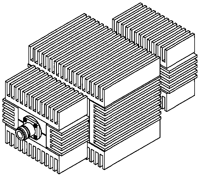
[0038] Disclosed in one or more embodiments is a split type flipped wideband power combiner based on composite function curve ridges, the simulation structure of which is as follows Figure 4 As shown, the power combiner itself is a complete whole, including an output port (synthesis port) and several input ports, and the orientation of the input port and the output port is consistent. Taking 8-way input as an example: the input port is on the edge of the large disc. 8 independent and evenly distributed 3.5mm connectors, each of the 8-way connectors couples the input signal of equal amplitude and phase to the coaxial space inside the disc through the coaxial probe, and further connects the 8 connectors in the coaxial space. The power of the channel signal is combined, and the final combined high-power signal is output through the standard N-type connector. At the same time, 8 identical composite function ridges are introduced into the coaxial expansion cavity to further reduce ...

Embodiment 2

[0056] A power amplifier disclosed in one or more embodiments, such as Figure 9 As shown, it includes: the active power amplifying device and the power combiner in Embodiment 1. Since the input port and the output port of the power combiner are in the same direction, the cable connecting the power combiner and the active power amplifying device is smooth and A C-shaped arc connection with small force rather than a S-shaped arc connection with a twist and a large force (such as Figure 8 As shown), it avoids the operation of repeated bending during the cable connection process, which is conducive to the stable transmission of signals, and can effectively shorten the distance between the power combiner and the radiator and the length of the cable, with compact structure and high reliability.

[0057] As an independent module, the synthesizer is connected to the power amplifier module through a coaxial cable, and the space layout of the power amplifier module is more free and fl...

Embodiment 3

[0059] A power divider disclosed in one or more embodiments, on the basis of the structure of the power combiner in Embodiment 1, the signal input port of the power combiner is used as the signal output port of the power divider, and the signal output port of the power combiner The signal output port is used as the signal input port of the power divider, that is, the signal input port and the output port of the power combiner are interchanged to realize power distribution.


PUM


Abstract

The invention discloses a flip-type broadband power combiner based on a composite function curve ridge. The flip-type broadband power combiner comprises a plurality of electromagnetic signal input ports uniformly distributed in the same circular plane and having the same distance to the center of circle, wherein each input port is connected to a coupling probe disposed in an elliptic function gradual cavity; all elliptic function gradual cavities are connected to an output port; and the output port is disposed at the center of circle. The flip-type broadband power combiner can solve the difficulty in high power combination in an ultra-wide frequency band and the heat dissipation of a high-power high-density heat source. The power combiner of the invention is wide in operating frequency band, low in insertion loss, large in the number of combining channels, high in combining efficiency. The power distribution, the power amplification and the power combination are separately designed. The flip-type broadband power combiner many advantages such as high heat dissipation efficiency, simple and compact structure, and easy processing and assembly.

Description

technical field [0001] The invention relates to the technical field of multi-channel power amplification and power combination, in particular to a flip-type broadband power combiner based on a composite function curve ridge. Background technique [0002] As an important part of microwave and millimeter wave radar, guidance, communication, and testing systems, microwave and millimeter wave solid-state power amplifiers have become an important research direction in the field of microwave and millimeter waves. With the continuous improvement of the output power requirements of the amplifier, due to the limitation of the power amplifier chip by its own semiconductor physical characteristics, as well as the influence of heat dissipation, manufacturing process and impedance matching, the single-chip amplifier often cannot meet the high-power application requirements in actual engineering. . Therefore, in order to meet the needs of high-power communication, testing and other syste...

Claims


Application Information

Patent Timeline
Patent Type & Authority Applications(China)
IPC IPC(8): H01P5/16
CPCH01P5/16
Inventor 王增瑞宁曰民朱伟峰
Owner THE 41ST INST OF CHINA ELECTRONICS TECH GRP
Learn More