Embedded microfluidic cooling channels inside optical components

A technology of optical components and cooling channels, applied in optical components, optics, instruments, etc., can solve problems such as thermal damage, thermal distortion of optical components, and restrictions on laser technology, and achieve low power consumption, high temperature control efficiency, and large heat dissipation area big effect

Active Publication Date: 2020-11-10
SHANGHAI INST OF OPTICS & FINE MECHANICS CHINESE ACAD OF SCI
View PDF6 Cites 0 Cited by
  • Summary
  • Abstract
  • Description
  • Claims
  • Application Information

AI Technical Summary

Problems solved by technology

[0005] In summary, the thermal distortion and thermal damage of optical components under high-energy laser irradiation seriously restrict the development of laser technology in the direction of high power and miniaturization

Method used


Image

  • Embedded microfluidic cooling channels inside optical components

Examples


Embodiment Construction

[0019] The present invention will be further described below in conjunction with the embodiments and accompanying drawings, but the protection scope of the present invention should not be limited thereby.

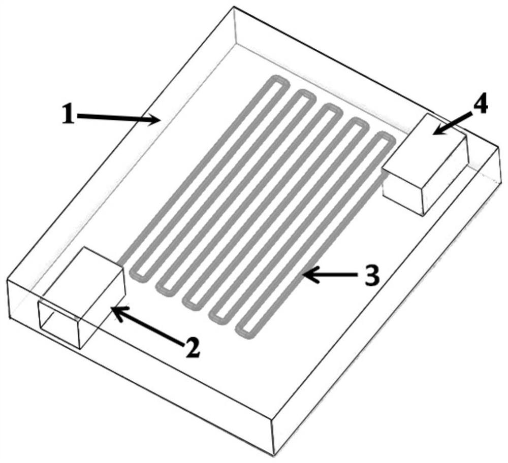
[0020] see figure 1 , as can be seen from the figure, the optical element of the present invention is embedded with a microfluid heat dissipation channel, and a connected microfluid heat dissipation channel 3 is prepared inside the optical element 1 by using femtosecond laser processing technology. The microfluid heat dissipation channel 3 has a liquid injection Inlet 2 and Outlet 4.

[0021] The optical element 1 is an optical element prepared from optical glass, single crystal silicon, or germanium sheet, or an optical element coated with an optical thin film.

[0022] The diameter of the microfluid cooling channel 3 ranges from 1 μm to 1000 μm.

[0023] The liquid is cooling oil or water.

[0024] The purpose of the present invention is to make the liquid flow in from...


PUM

PropertyMeasurementUnit
diameteraaaaaaaaaa

Abstract

A microfluid heat dissipation channel embedded in an optical element, using femtosecond laser processing technology to prepare a connected microfluid heat dissipation channel inside the optical element, the microfluid heat dissipation channel has a liquid injection port and an output port. The temperature control of the optical element by the present invention has the advantages of small size, large heat dissipation area, and low power consumption; in addition, the microfluid heat dissipation channel can be placed near the surface of the optical element to further improve the surface temperature control ability of the element; it is especially suitable for high-power laser radiation Heat control during irradiation improves the ability of optical components to resist thermal distortion and thermal damage.

Description

technical field [0001] The invention relates to heat dissipation of an optical element, in particular to a microfluid heat dissipation channel embedded in an optical element. Background technique [0002] As high-energy laser technology is more and more widely used in military and civilian fields, the output of high-power, miniaturized, and high-beam-quality laser beams has put forward higher and higher requirements for the ability of optical components to resist thermal distortion and thermal damage. The heat absorption deformation of optical components under the action of strong laser is an unavoidable objective reality, and it will become more and more serious with the increase of laser power, and finally become the constraint condition of strong laser output power and beam quality. For laser cavity mirrors, there are currently two main technical approaches to reduce thermal deformation: one method is to enhance the heat dissipation capability of the cavity mirror, and th...

Claims


Application Information

Patent Timeline
Patent Type & Authority Patents(China)
IPC IPC(8): G02B7/00G02B5/00
CPCG02B7/008G02B5/00
Inventor 胡国行聂兆刚贺洪波张芳腾曹珍邵建达
Owner SHANGHAI INST OF OPTICS & FINE MECHANICS CHINESE ACAD OF SCI
Why Eureka
Try Eureka