Method for recycle gas condensation and liquid nitrogen separation of synthesis ammonia

A technology of condensation separation and circulating gas, which is applied in the directions of refrigeration and liquefaction, liquefaction, solidification, etc., can solve the problems that the ammonia ice machine refrigeration technology cannot satisfy the condensation of circulating gas and separation of liquid ammonia, and achieve good chemical stability and safety. The effect of large cooling capacity and small compression ratio

Pending Publication Date: 2019-04-12
SHANDONG RUNYIN BIOCHEM
View PDF5 Cites 0 Cited by
  • Summary
  • Abstract
  • Description
  • Claims
  • Application Information

AI Technical Summary

Problems solved by technology

[0004] The applicant cooperated with a company in Nanjing to build a 600,000-ton / year synthetic ammonia production device in the applicant company. For such a large-scale synthetic ammonia system, the traditional ammonia ice machine refrigeration technology cannot meet the needs of circulating gas condensation and liquid ammonia separation.

Method used


Image

  • Method for recycle gas condensation and liquid nitrogen separation of synthesis ammonia

Examples


Embodiment 1

[0028] This embodiment is a method for condensing and separating liquid ammonia from the circulating gas of synthetic ammonia, and the specific steps include:

[0029] S1) CO 2 Compression boost of gas:

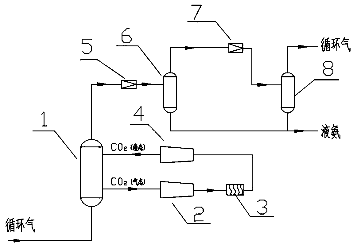
[0030] Select CO 2 Gas is used as the medium to provide cooling capacity, and the centrifugal compressor driven by the steam turbine is selected as the supercharger, and the CO 2 The gas first enters the compressor 2, the initial pressure P 1 =1.87 MPa, volume flow V 1 =12693.8 M3 / h, temperature T 1 =-20℃

[0031] In this embodiment, the steam pressure of the driving steam turbine is P=3.82 MPa, the steam consumption is 7t / h, and the shaft power is 1430KW.

[0032] CO 2 After the gas is compressed by compressor 2, P 2 =2.62 MPa, volume flow V 2 =16936 M3 / h, temperature T 2 =52°C, it can be known that CO 2 The gas obtains 5148MJ energy through compressor 2.

[0033] S2) Compressed CO 2 The heat exchange pressure between the gas and the cold water through the corru...

Embodiment 2

[0040] CO in this example 2 The volume of gas, the pressure of initial circulating gas are all identical with embodiment one, and concrete steps comprise:

[0041] S1) CO2 gas is passed into the compressor 2 to compress and cool down; the CO 2 The initial pressure of the gas P 1 =1.85MPa, temperature T 1 =-18°C, the CO after being compressed by compressor 2 2 Gas pressure P 2 =2.60MPa, temperature T 2 =50°C.

[0042] S2) The compressed CO 2 The gas passes into the corrugated plate heat exchanger 3, and the CO after heat exchange with cold water 2 Gas pressure P 3 =P 2 , temperature T 3 down to 39°C.

[0043] S3) CO after cooling 2 The gas makes gaseous CO in an isentropic expansion system 2 Condensed into a liquid state; the isentropic expansion system includes an impeller type isentropic expander 4, and the high-pressure CO 2The temperature of the gas in the isentropic expander 4 in the adiabatic state drops through the impeller to make the gaseous CO 2 Condens...

Embodiment 3

[0049] In this embodiment, the volume of CO2 gas and the pressure of the initial circulating gas are all the same as in Embodiment 1, and the specific steps include:

[0050] S1) CO 2 The gas is passed into the compressor 2 to compress and cool down; The CO 2 The initial pressure of the gas P 1 =1.88MPa, temperature T 1 =-19°C, the CO after being compressed by compressor 2 2 Gas pressure P 2 =2.64MPa, temperature T 2 =55°C.

[0051] S2) The compressed CO 2 The gas exchanges heat with cold water, making the CO 2 Gas cooling; the cold water heat exchange method is to CO 2 The gas passes into the corrugated plate heat exchanger 3, and the CO after heat exchange with cold water 2 Gas pressure P 3 =P 2 , temperature T 3 down to 42°C.

[0052] S3) CO after cooling 2 The gas makes gaseous CO in an isentropic expansion system 2 Condensed into a liquid state; the isentropic expansion system includes an impeller type isentropic expander 4, and the high-pressure CO 2 The...


PUM


Abstract

The invention relates to the technical field of synthesis nitrogen production, and directly relates to a method for recycle gas condensation and liquid nitrogen separation of synthesis ammonia. The method includes the following steps that (1) the CO2 gas is led into a compressor so as to compress and cool; (2) heat exchanging is conducted on the compressed CO2 gas and cold water, so that the CO2 gas is cooled; (3) the cooled CO2 gas condenses the gaseous CO2 into the liquid in an equal entropy expansion system; (4) the circulating gas and the CO2 are mixed and condensed to the liquid nitrogen;(5) the circulating gas continues to separate the liquid nitrogen to enter a nitrogen warehouse after the pressure and temperature of a primary throttle valve are reduced, and the non-condensed circulating gas is then depressurized and cooled through a secondary throttle valve; and (6) after the secondary throttling expansion refrigeration, the circulating gas is condensed to the liquid nitrogen, and then is separated to enter the nitrogen warehouse, and the non-condensed remaining circulating gas is again led into a circulating condenser to be used. The liquid nitrogen separating method hashigh refrigeration capacity and low energy consumption so as to meet the needs of circulating gas condensation and liquid nitrogen separation of a large nitrogen synthesis device.

Description

technical field [0001] The invention relates to the technical field of synthetic ammonia production, and directly relates to a method for condensing and separating liquid ammonia from circulating gas of synthetic ammonia. Background technique [0002] Synthetic ammonia is a raw material for fertilizers and various chemical products. my country's synthetic ammonia production has reached 70 million tons per year, accounting for 43% of the world's synthetic ammonia production, and occupies an extremely important position in the national economy. [0003] In order to increase the output of synthetic ammonia for many years, ammonia synthesis technology has been pursuing high-pressure synthesis, which has caused defects such as high resistance and high energy consumption in the synthesis system. In recent years, the research on synthetic ammonia technology at home and abroad is developing towards large scale and low pressure, which has played a positive role in energy saving and c...

Claims


Application Information

Patent Timeline
Patent Type & Authority Applications(China)
IPC IPC(8): F25J1/00F25J1/02
CPCF25J1/0027F25J1/0279
Inventor 林迥何树文李思华李强袁宽刘兴平胡茂龙李华
Owner SHANDONG RUNYIN BIOCHEM
Why Eureka
Try Eureka