Eureka AIR delivers breakthrough ideas for toughest innovation challenges, trusted by R&D personnel around the world.

A single-direction double-action high-frequency vibration hot-press vacuum sintering furnace

A vacuum sintering furnace, high-frequency vibration technology, applied in the direction of furnace, charge, muffle furnace, etc., can solve the problems of difficult control of vibration pressure of cam vibration sintering furnace, high frequency response requirements of servo valve, high cost of hardware equipment, etc. Achieve the effects of easy control of vibration pressure, large vibration amplitude and low cost

Active Publication Date: 2019-10-29
JINGDEZHEN CERAMIC UNIV
View PDF7 Cites 2 Cited by
  • Summary
  • Abstract
  • Description
  • Claims
  • Application Information

AI Technical Summary

Problems solved by technology

For example, the vibration amplitude and pressure of the electromagnetic vibration sintering furnace are relatively small; the vibration pressure of the cam vibration sintering furnace is difficult to control, and the service life is low; Frequency, heavy load vibration and pressurization, the equipment has extremely high requirements on the frequency response of the servo valve, and the flow rate of the servo valve is also high, resulting in high cost of the loaded hardware equipment
At the same time, the vibration direction of the above-mentioned sintering furnace generally adopts a single-acting vibration mode toward the mold, and the vibration loading pressure is much lower than the static load pressure, which directly affects the compactness of the powder

Method used


Image

  • A single-direction double-action high-frequency vibration hot-press vacuum sintering furnace
  • A single-direction double-action high-frequency vibration hot-press vacuum sintering furnace
  • A single-direction double-action high-frequency vibration hot-press vacuum sintering furnace

Examples


Embodiment Construction

[0027] Attached below Figure 1-3 The present invention is described in further detail with specific embodiment:

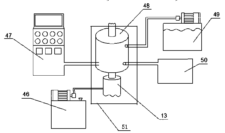
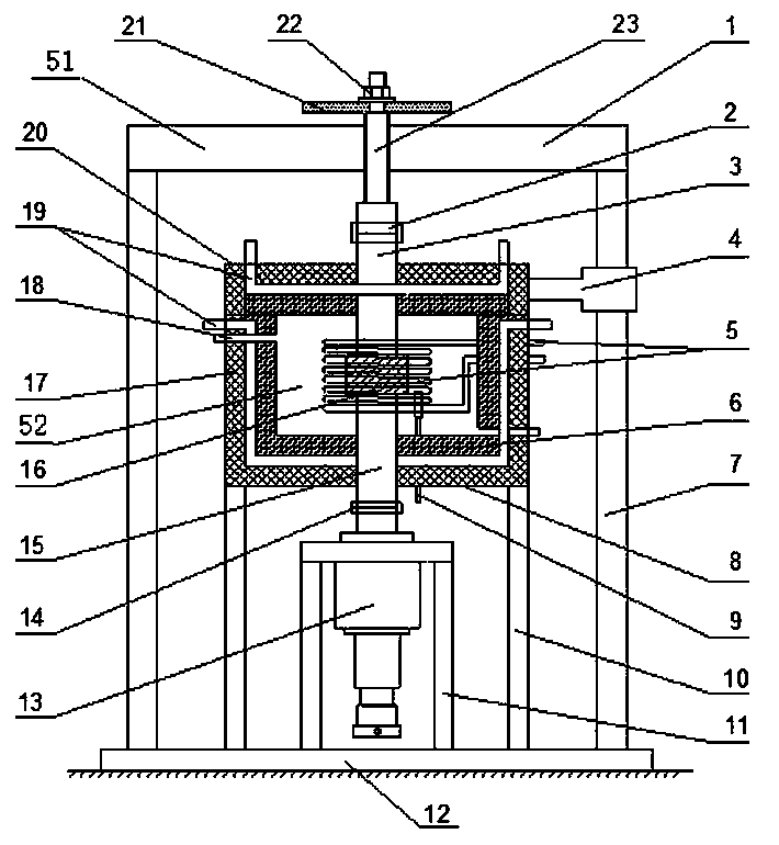
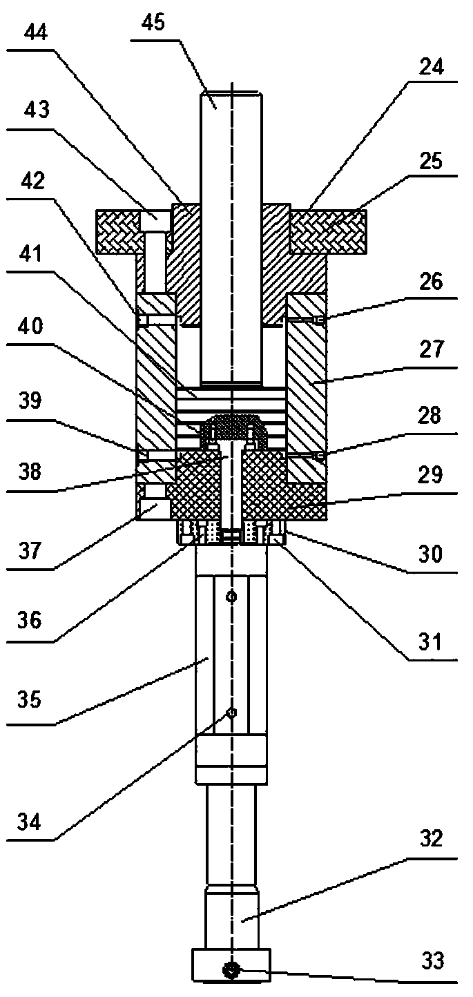
[0028] A single-direction double-action high-frequency vibration hot-press vacuum sintering furnace, including a control center 47, a hydraulic station 46, a cooling water station 49, a vacuum 50, a furnace body 48, a high-frequency vibration pressurization device 13, and a furnace frame 51, The furnace body 48 and the high-frequency vibration pressurizing device 13 are arranged inside the furnace frame 51 , and the control center 47 , the cooling water station 49 , and the hydraulic station 46 of the vacuum pump 50 are respectively arranged outside the furnace frame 51 .

[0029] The grate 51 is composed of a beam 1, a beam pillar 7, and a base 12, and the beam pillar 7 is vertically welded between the base 12 and the beam 1;

[0030] The body of furnace 48 is composed of connecting flange 2, upper pressure head 3, hinged connecting rod 4, induction coil 5, insu...


PUM


Abstract

The invention relates to a one-way double-acting high-frequency vibration hot-pressing vacuum sintering furnace. The one-way double-acting high-frequency vibration hot-pressing vacuum sintering furnace comprises a control center (47), a hydraulic station (46), a cooling water station (49), a vacuum extractor (50), a furnace body (48), a high-frequency vibration boosting device (13) and a furnace frame (51). The control center (47), the cooling water station (49) and the vacuum extractor (50) are connected with the furnace body (48), the hydraulic station (46) is connected with the high-frequency vibration boosting device (13), the high-frequency vibration boosting device (13) is connected with the furnace body (48), and the furnace body (48) and the high-frequency vibration boosting device(13) are arranged in the furnace frame (51). According to the sintering furnace, high-performance ceramic, metal and some refractory metal compound products are prepared in the manner that high-frequency vibration and static load pressure are combined, the one-way double-acting high-frequency vibration hot-pressing vacuum sintering furnace has the beneficial effects that the vibration amplitude is large, vibration pressure is easy to control, the precision is high, and the cost is low, and therefore broad market prospects are achieved.

Description

technical field [0001] The invention relates to the technical field of vacuum hot-press vibration sintering furnace, in particular to a single-direction double-action high-frequency vibration hot-press vacuum sintering furnace. Background technique [0002] At present, the working method of the vacuum hot-pressing sintering furnace is to pack the powder of ceramics, metals and some refractory metal compounds into a pre-prepared hot-pressing mold for compaction, and then put the mold and the powder into the vacuum hot-pressing sintering furnace It is directly heated and formed in the heating chamber. This processing technology is simple and convenient. However, the obtained product has low density, low strength and hardness, and poor product performance. In order to overcome these shortcomings, sintering furnaces such as cam vibration sintering furnaces, electromagnetic vibration sintering furnaces, and hydraulic vibration sintering furnaces have emerged. These sintering fu...

Claims


Application Information

Patent Timeline
Patent Type & Authority Patents(China)
IPC IPC(8): F27B5/05F27B5/06F27B5/18
CPCF27B5/04F27B5/06F27B5/18F27B2005/064F27M2003/04
Inventor 王兴国谢地荣吴南星黄志诚
Owner JINGDEZHEN CERAMIC UNIV
Why Eureka
Eureka Blog
Learn More