PFM control-based booster system response speed conversion circuit and control method thereof

A technology of response speed and conversion circuit, which is applied in the field of PFM control-based boost system response speed conversion circuit and its control, and can solve problems such as large inductance, reduced market competitiveness, and slow response speed of comparators.

Pending Publication Date: 2019-04-12
QX MICRO DEVICES
View PDF5 Cites 9 Cited by
  • Summary
  • Abstract
  • Description
  • Claims
  • Application Information

AI Technical Summary

Problems solved by technology

[0003] Since the PFM-controlled boost system requires extremely low quiescent current in standby or light load, the bias currents of the comparator and the zero-crossing detection comparator are designed to be very small, resulting in a slow response speed of the two comparators. , which limits the operating frequency of the system, thus requiring larger inductors and larger output capacitors
[0004] The disadvantages of traditional technology are: using large inductance and large capacitance to achieve low ripple, low standby current, and strong load capacity, which leads to an increase in system cost, and the large size of the system also limits the application in compact applications. reducing the competitiveness of the market

Method used


Image

  • PFM control-based booster system response speed conversion circuit and control method thereof
  • PFM control-based booster system response speed conversion circuit and control method thereof
  • PFM control-based booster system response speed conversion circuit and control method thereof

Examples


Embodiment Construction

[0048] The present invention will be described in further detail below in conjunction with accompanying drawing:

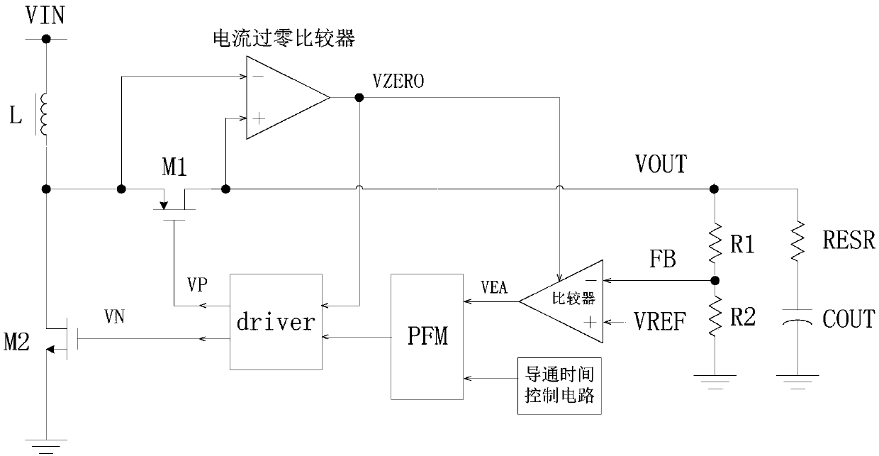
[0049] Please refer to figure 2 , which is the first technical solution of the present invention, provides a PFM-based boost converter response speed conversion circuit, which passes the output signal V of the internal current zero-crossing comparator ZERO Differentiate the load is light load or heavy load, thereby changing the bias current of the comparator.

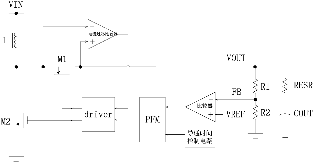
[0050] Please refer to figure 2 , the circuit includes: voltage input V IN , inductance L, current zero-crossing comparator, rectifier tube M 1 , power tube M 2 , drive circuit driver, PFM module, comparator, voltage divider resistor R 1 , R 2 , output capacitance C OUT , On-time control circuit, also includes output capacitor internal resistance R ESR , the rectifier M 1 PMOS tube, power tube M 2 It is an NMOS tube; the voltage input terminal V IN Sequentially through the inductor L, the recti...


PUM


Abstract

The invention relates to a PFM control-based booster system response speed conversion circuit and a control method thereof; the partial voltage at the output end of a circuit is used as a sampling voltage to be compared with the reference voltage of a comparator; an output signal of the comparator and an output signal of a conduction time control circuit act on a PFM module; an output signal of the PFM module and an output signal of a current zero-crossing comparator act on conduction or cut off of a control power tube or a rectifying tube of the driving circuit; when the output end voltage islower than a preset voltage, the power tube is conducted, the rectifying tube is cut off, an inductor performs energy storage and the conduction time control circuit starts timing; and after the preset time is reached, the conduction time control circuit is used for resetting the PFM module to control the driving circuit, the power tube is cut off, the rectifying tube is conducted, and the inductor releases energy to the output end. A load is judged to be a light load or a heavy load according to the duty ratio of the output signal of the current zero-crossing comparator or the output drivingsignal of the driving circuit, the bias current of the comparator is reduced during the light load, and the bias current of the comparator is increased during the heavy load.

Description

technical field [0001] The invention relates to the field of electronic circuits, in particular to a PFM control-based boost system response speed conversion circuit and a control method thereof. Background technique [0002] With the continuous improvement of the integration level of the digital processing unit of the system on chip, such as integrating DSP and ARM into the same chip, the requirements for the load capacity and efficiency of the power system are getting higher and higher. When developing battery-powered portable electronic devices, such as mobile phones, MP4, EBOOK, GPS and other low-power products, if the power system design is not reasonable, it will affect the entire system architecture, product function combination, software design and power distribution architecture etc. Portable products are powered by batteries in most cases. There are two implementations of DC / DC and LDO for power management at the back end of the battery, each with its own advantag...

Claims


Application Information

Patent Timeline
Patent Type & Authority Applications(China)
IPC IPC(8): H02M3/158H02M1/088
CPCH02M1/088H02M3/158H02M1/0048Y02B70/10
Inventor 吴玉强黄朝刚
Owner QX MICRO DEVICES
Why Eureka
Try Eureka