Endoscopy imaging system and method based on single multimode fiber

A multi-mode optical fiber and imaging system technology, applied in the direction of endoscopes, optics, optical components, etc., can solve the problems of large probe size and long time for batch focusing of light spots, and achieve the effect of reducing image acquisition time and avoiding iterative calculation

Inactive Publication Date: 2019-04-16
XI'AN INST OF OPTICS & FINE MECHANICS - CHINESE ACAD OF SCI +1
View PDF5 Cites 8 Cited by
  • Summary
  • Abstract
  • Description
  • Claims
  • Application Information

AI Technical Summary

Problems solved by technology

[0010] In order to solve the problem that the existing optical fiber endoscopic imaging technology has a large probe size, it is difficult to meet the application requirements, and when using focused spot scanning imaging, due to point-by-point scanning, multiple iterative calculations, repeated visits to peripherals, and the time it takes to form a batch of focused spots Long technical problem, the present invention provides an endoscopic imaging system and method based on a single multimode optical fiber, using a single multimode optical fiber as a probe, due to the small diameter of the probe, it can enter a narrow cavity to image the target; and use Wide-field imaging method, no scanning operation is required to acquire the target image, so it has the advantage of short image acquisition time

Method used


Image

  • Endoscopy imaging system and method based on single multimode fiber
  • Endoscopy imaging system and method based on single multimode fiber
  • Endoscopy imaging system and method based on single multimode fiber

Examples


Embodiment Construction

[0071] The present invention proposes an endoscopic imaging system and method based on a single multimode optical fiber, which is divided into two parts: an imaging system and an imaging method. Figures 1 to 6 Introduce them one by one.

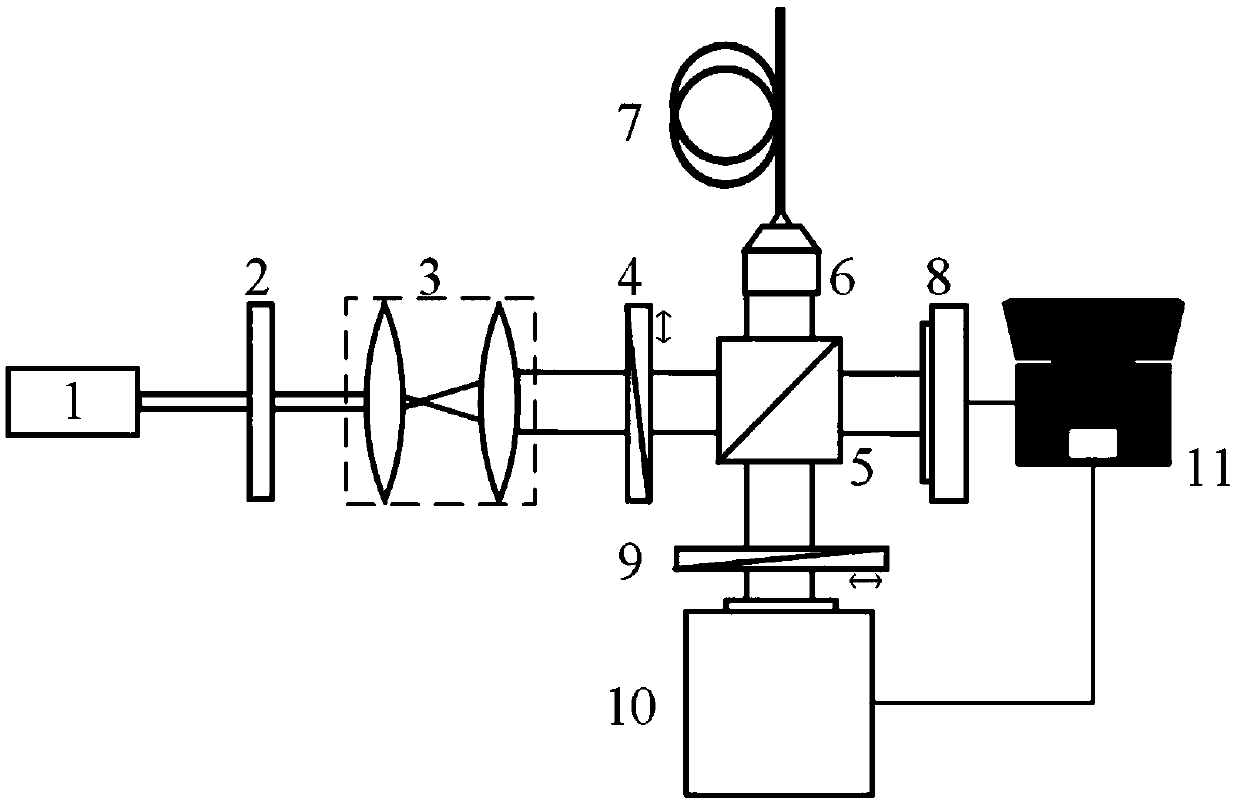
[0072] Part 1: Imaging system (such as figure 1 shown)

[0073] The endoscopic imaging system based on a single multimode optical fiber of the present invention includes an illumination system, a light field measurement system and a computer processing system 11 .

[0074] The illumination system is used to provide a linearly polarized laser light source, including a laser 1 , an optical attenuator 2 , a collimator beam expander 3 and a first linear polarizer 4 arranged in sequence.

[0075] The light field measurement system is an interference optical path, including a beam splitter 5, a reference arm, an object light arm, a second linear polarizer 9 and a camera 10; the beam splitter 5 is used to divide the laser light source output by t...


PUM


Abstract

In order to solve the technical problems that according to an existing endoscopy imaging technology, the size of a probe is large, the application requirement cannot be met, and when focusing spot scanning imaging is adopted, due to point-by-point scanning, repeated iterative computation and repeated access peripheral, the time spent in forming batched focusing spots is long, the invention provides an endoscopy imaging system and method based on single multimode fiber. The system comprises an illumination system, a light field measuring system and a computer processing system; the illuminationsystem comprises a laser, an optical attenuator, a collimating and beam expander and a first line polarizing film which are arranged in sequence; the light field measuring system comprises a beam splitter, a reference arm, an objective light arm, a second line polarizing film and a camera; the reference arm is composed of an optical phase shifter; the objective light arm comprises a focusing objective lens and the single multimode fiber; the computer processing system is used for controlling an optical phase shifter and a camera, an interference light field is demodulated through the phase shifting interference method, an objective light composite light wave electric field is obtained, and imaging is performed.

Description

technical field [0001] The invention relates to endoscopic imaging technology, in particular to an endoscopic imaging system and method based on a single multimode optical fiber. Background technique [0002] Endoscopes are widely used in imaging and detection in medical and industrial fields because they can image internal objects through narrow cavities. The current mainstream medical endoscopes are based on fiber optic bundle systems or complex mechanical scanning systems. The separation of the illumination optical path and the image transmission optical path leads to a large probe size, which is difficult to meet the requirements of modern medicine for minimally invasive and non-invasive disease diagnosis and treatment. Probe requirements; similarly, current industrial endoscopes also require ultra-fine endoscopic probes. [0003] Multimode fiber has multiple spatial modes and can transmit information in parallel, so it is considered to have the potential to be used for...

Claims


Application Information

Patent Timeline
IPC IPC(8): A61B1/00A61B1/06A61B1/07G02B23/24G03H1/04
CPCA61B1/00064A61B1/00131A61B1/00165A61B1/0661A61B1/07G02B23/2461G02B23/2469G03H1/0443
Inventor 任立勇许程访庄斌贺正权
Owner XI'AN INST OF OPTICS & FINE MECHANICS - CHINESE ACAD OF SCI
Why Eureka
Try Eureka