
Vertical distribution hidden type stirring station for subway construction

A concealed mixing station technology, which is applied in the field of vertically distributed concealed mixing stations for subway construction, can solve the problems of long air transmission distance, constraints on the production capacity, popularization rate and regionality of concrete mixing stations, and large floor area. Achieve the effect of saving land use cost, improving land use efficiency and reducing land occupation

Inactive Publication Date: 2019-04-16
CHINA RAILWAY TUNNEL GROUP CO LTD +1
View PDF5 Cites 0 Cited by
  • Summary
  • Abstract
  • Description
  • Claims
  • Application Information

AI Technical Summary

Problems solved by technology

[0003] The concrete mixing plant in the prior art, the material storage device, the mixing device and other large-scale equipment are relatively high on the ground. Although the tanker can be loaded with the blanking type, the powder tank is built at a high place, and the material needs to be lifted. For aggregates such as sand and gravel, an additional conveying device is required to lift the material to the material inlet of the mixing machine. The lifting height is large and the air transmission distance is long, which brings many problems, such as large floor area, difficult vibration and noise. Isolation, high equipment, inconvenient material lifting, etc.
Generally speaking, the existing equipment is not conducive to energy saving and emission reduction, reducing energy consumption of enterprises and improving production efficiency. At the same time, problems such as earthquake resistance and wind speed caused by the excessive height of the equipment need to be considered, which leads to the shape of each device , The volume is limited, which greatly restricts the capacity, popularity and regionality of concrete mixing plants

Method used


Image

  • Vertical distribution hidden type stirring station for subway construction
  • Vertical distribution hidden type stirring station for subway construction
  • Vertical distribution hidden type stirring station for subway construction

Examples


Embodiment Construction

[0024] The technical solutions of the present invention will be further described in detail below in conjunction with specific embodiments.

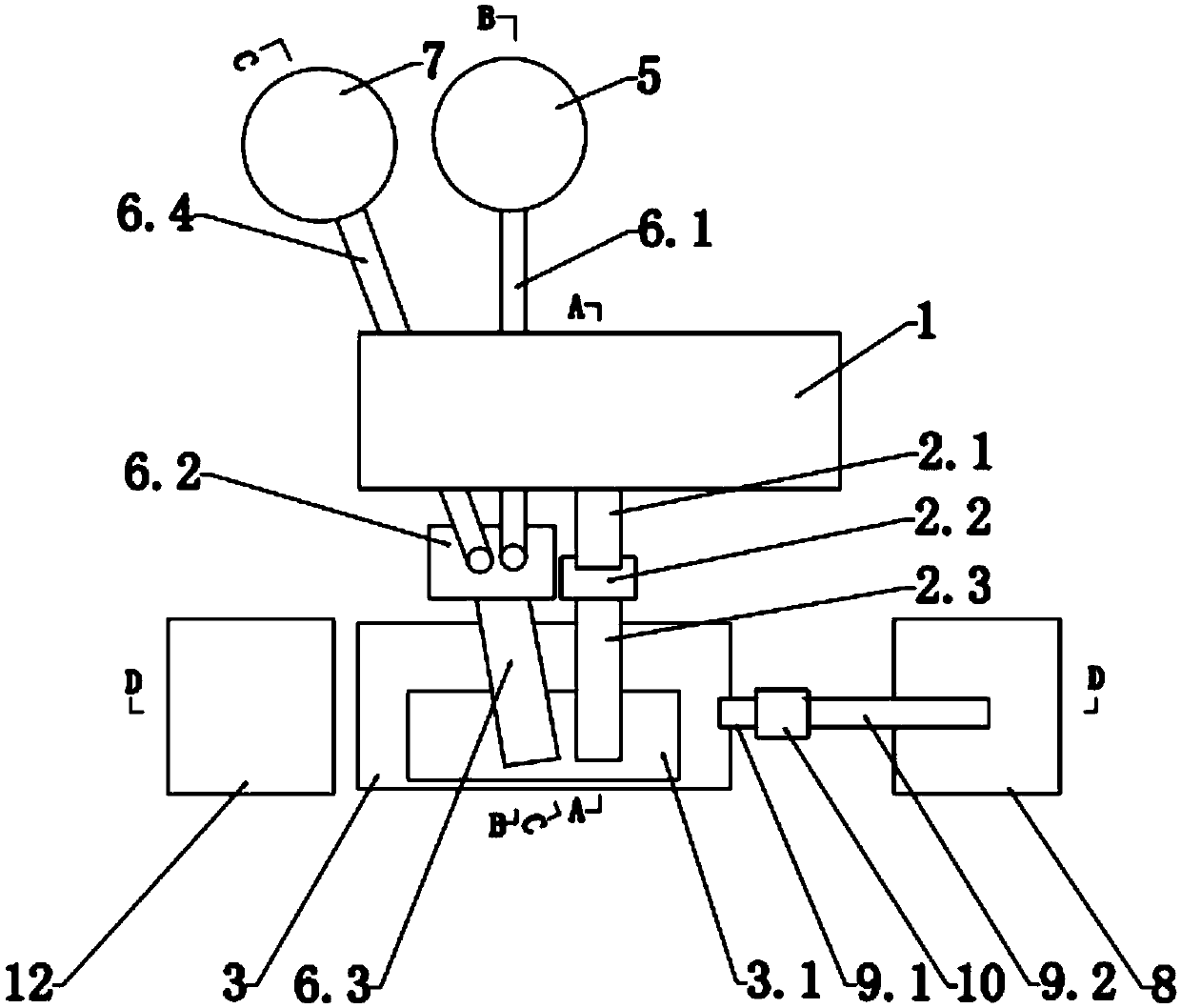
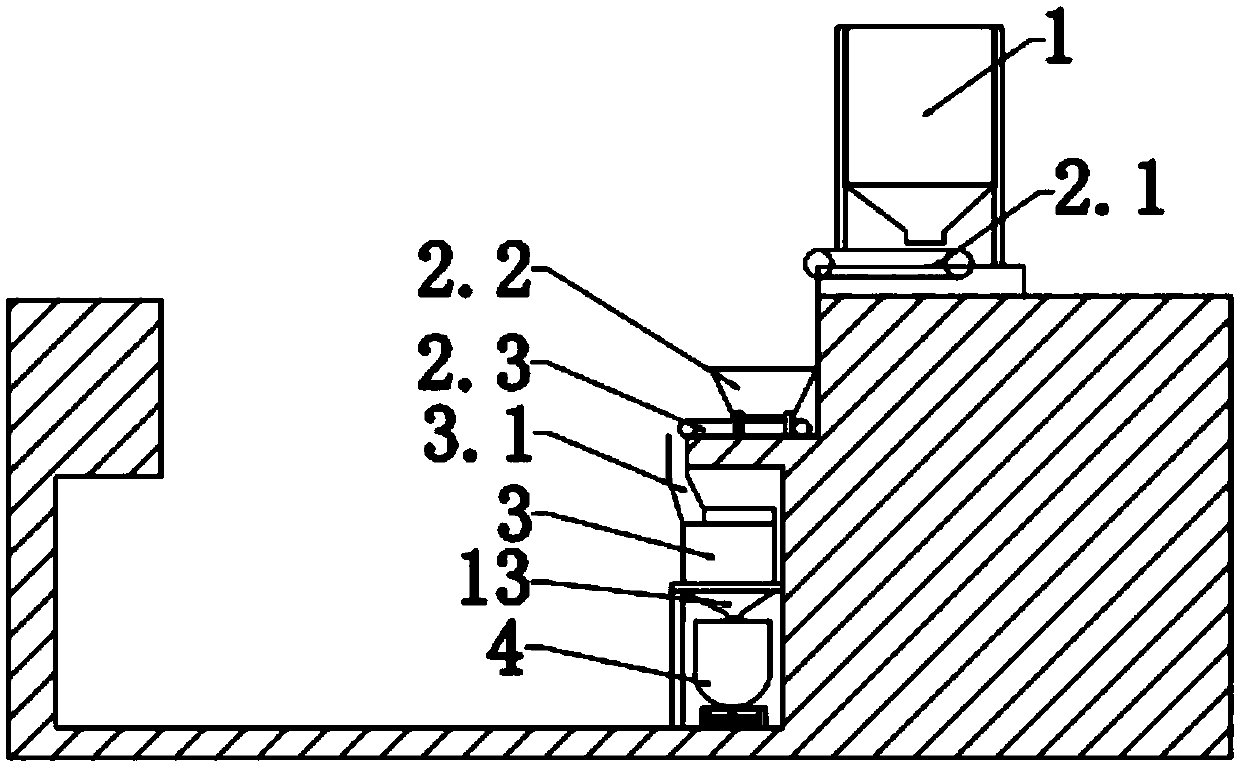
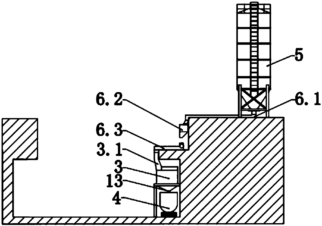
[0025] As shown in the figure, a vertically distributed concealed mixing station for subway construction, including a mixing system, a powder system, and an aggregate system;

[0026] The mixing system is located below the ground, and the mixing system includes a mixer 3. A discharge device 13 is provided below the mixer 3. A mortar truck 4 is provided below the discharge device 13. A water tank 8 is provided on one side of the mortar truck 4, and a water tank 8 It communicates with the mixer 3 through pipelines, wherein the unloading device 13 is a hopper, and the pipelines include a first pipeline 9.1 and a second pipeline 9.2. One end of the second pipeline 9.2 is connected to the water tank 8, and the second pipeline 9.2 The other end of the water scale is connected with a water scale 10, and the bottom end of the water scale 10 is c...


PUM


Abstract

The invention discloses a vertical distribution hidden type stirring station for subway construction. The vertical distribution hidden type stirring station comprises a stirring system, a powder system and an aggregate system, wherein the stirring system is arranged below the ground, the stirring system comprises a stirring machine, a discharging device is arranged below the stirring machine, a mortar trolley is arranged below the discharging device, a water bin is arranged on one side of the mortar trolley, the water bin communicates with the stirring machine through a pipeline, an operationchamber is further arranged on one side of the stirring machine, the operation chamber is used for controlling the operation of the stirring station, the powder system comprises a powder bin, the powder bin is arranged on the ground, the powder bin communicates with the stirring machine through a first transferring device, the aggregate system comprises an aggregate batching machine, the aggregatebatching machine is arranged on the ground, and the aggregate batching machine communicates with the stirring machine through a second transferring device. According to the vertical distribution hidden type stirring station, the noise pollution can be reduced, the transportation height of initial materials can be reduced, and the occupied area can be reduced.

Description

technical field [0001] The invention relates to the technical field of mixing stations, in particular to a vertically distributed concealed mixing station for subway construction. Background technique [0002] Concrete mixing plant is a combined device used to centrally mix concrete, and it is an indispensable large-scale equipment in engineering construction and production. Because of its high degree of mechanization and automation, its productivity is also high, and it can ensure the quality of concrete and save cement. It is often used in large and medium-sized water conservancy, electric power, bridges and other projects with large concrete engineering volume, long construction period, and concentrated construction sites. The concrete mixing plant for subway construction mainly provides mortar for synchronous grouting for tunneling of shield machines. [0003] The concrete mixing plant in the prior art, the material storage device, the mixing device and other large-scal...

Claims


Application Information

Patent Timeline
IPC IPC(8): B28C5/08B28C7/06B28C7/12B28C7/16
CPCB28C5/08B28C7/06B28C7/12B28C7/16
Inventor 张建王江波赵磊典军伟朱军建凌代铭
Owner CHINA RAILWAY TUNNEL GROUP CO LTD
Learn More