Power-off type electric leakage signal identification method and power-off type electric leakage indicating device

A technology for indicating devices and signal recognition, applied in measuring devices, measuring electricity, measuring electrical variables, etc., can solve problems such as failure to capture transient events caused by electric leakage

Pending Publication Date: 2019-04-16
南京钰吉电气科技有限公司
View PDF1 Cites 1 Cited by
  • Summary
  • Abstract
  • Description
  • Claims
  • Application Information

AI Technical Summary

Problems solved by technology

[0005] At present, there are other leakage detectors on the market, but they are all based on the principle of detecting steady-state leakage waveforms to realize leakage detection, and cannot capture transient events such as leakage caused by electric trips, and such instantaneous events are realistic configurations. The most common phenomenon in electrical operation

Method used


Image

  • Power-off type electric leakage signal identification method and power-off type electric leakage indicating device
  • Power-off type electric leakage signal identification method and power-off type electric leakage indicating device
  • Power-off type electric leakage signal identification method and power-off type electric leakage indicating device

Examples


Embodiment 1

[0080] This embodiment provides a power-off type leakage signal identification method, including the following steps:

[0081] S0. Acquisition of circuit residual current waveform: The residual current (referring to leakage current) comes from the current transformer (leak detection CT) that detects leakage current. It adopts conventional design, and the leakage detection CT passes through the phase wire (single-phase is live wire, three-phase is ABC phase line) and neutral line, when a leakage occurs, the leak detection CT will collect the leakage current, and the leakage current directly enters the primary "current limiting circuit unit" of the circuit;

[0082] S1, collecting the residual current waveform of the circuit;

[0083] S2, limiting the excessive current;

[0084] S3, performing a constant voltage bias on the differential amplifier;

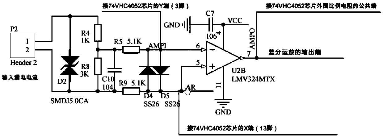
[0085] S4. Perform differential amplification with a bias voltage on the processed leakage current waveform, and the amplificatio...

Embodiment 2

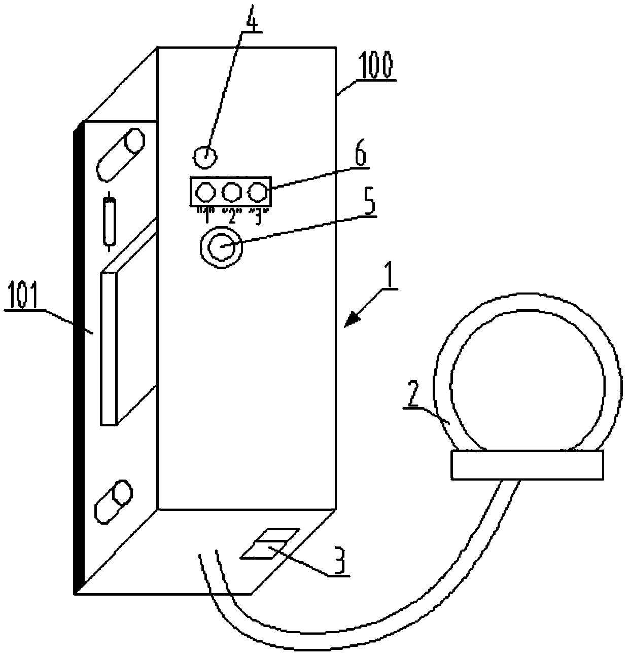
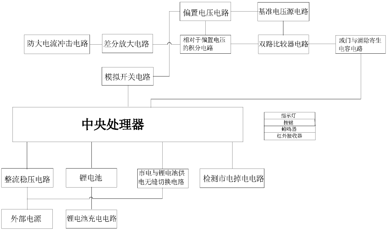
[0091] This embodiment provides a power-off type leakage indicator device using the power-off type leakage signal identification method of Embodiment 1, and its structure is as follows figure 1 and figure 2 As shown, it includes leakage indicator 1 and current transformer 2 (CT, that is, a current transformer for detecting leakage current). There is a special interface on leakage current indicator 1, and the two signal lines from current transformer 2 are connected to the leakage current indicator Interface connection on Device 1. The leakage indicator 1 includes a housing 100, a PCB board 101 arranged in the housing 100, and the PCB board 101 is integrated with an anti-large current impact circuit, a constant voltage circuit, a voltage bias circuit, a differential amplifier circuit with bias voltage, Integral circuit relative to bias voltage, dual comparator circuit, OR gate circuit, discharge parasitic charge resistor, central processing unit (preferably STM32F030KBT6). T...


PUM

PropertyMeasurementUnit
Diameteraaaaaaaaaa

Abstract

The invention relates to a power-off type electric leakage signal identification method. The method comprises the following steps: S1, acquiring a circuit residual current waveform; S2, carrying out current limiting on the overlarge current; S3, carrying out constant voltage biasing on a differential amplifier; S4, carrying out differential amplification on a leakage current waveform; S5, carryingout integral filtering relative to the bias voltage; S6, performing comparison operation with pre-stage output analog voltage by adopting a two-way comparator, so that positive and negative waves relative to the bias voltage are corrected into square waves in a positive voltage range after passing through the comparator; S7, performing OR operation on the two paths of comparison square waves; andS8, determining whether the signal is an electric leakage signal or not after the electric leakage characteristic is determined through a high-speed comparison recognition algorithm. The method has the advantages that the transient electric leakage characteristic can be quickly found, so that the electric leakage point can be accurately found, and misinformation and missing information are avoided.

Description

technical field [0001] The invention relates to a leakage indicator device, in particular to a power-off type leakage signal identification method and a power-off type leakage indicator device. Background technique [0002] It is understood that leakage is the current leakage caused by insulation damage or other reasons. Leakage will occur if there is a certain potential difference between the electrical shell and the live wire of the mains for some reason and the ground. [0003] At present, electricity leakage is common in power supply systems in rural areas and urban villages in my country. The state stipulates that at least rural power supply systems need to invest in total leakage protection in three-level leakage protection. However, due to the intermittent characteristics of leakage, it is difficult to locate the leakage point in time and accurately, resulting in the failure of the total leakage protection in many places, which seriously endangers the safety of power...

Claims


Application Information

Patent Timeline
IPC IPC(8): G01R31/02
CPCG01R31/50
Inventor 于建东杨晓松
Owner 南京钰吉电气科技有限公司
Why Eureka
Try Eureka