Interdigital longitudinal magnetic mode drift tube linear accelerator of separation focusing type

A linear accelerator and drift tube technology, which is applied in the direction of linear accelerators, accelerators, electrical components, etc., can solve the problems of low installation accuracy, large deviation between the center of the drift tube and the design value, and jamming, etc., to improve acceleration efficiency, The structure of the cavity is simple, and the effect of accelerating the gradient is improved

Inactive Publication Date: 2019-04-16
TSINGHUA UNIV
View PDF3 Cites 7 Cited by
  • Summary
  • Abstract
  • Description
  • Claims
  • Application Information

AI Technical Summary

Problems solved by technology

[0010] In the currently published technical information, there are two methods for preparing the drift tube containing the permanent magnet quadrupole magnet and the support rod: the first method is to install the permanent magnet quadrupole magnet in the drift tube, and then use a drift tube with a magnetic shielding device. The drift tube and the end cap are welded by electron beam to form a drift tube assembly; this processing method is characterized by the use of a magnetic shielding device, which is used to shield the influence of the magnetic field of the permanent magnet on the electron beam current and ensure the reliability of welding; but due to The use of magnetic shielding devices makes the process of electron beam welding more complicated and requires processing and installation of additional magnetic shielding tools
The second method is to install the permanent quadrupole magnet by thermal expansion and contraction. The drift tube using this processing method is mainly divided into two parts, the drift tube jacket with the support rod and the permanent magnet quadrupole magnet. The inner sleeve of the drift tube of the pole magnet, put the inner sleeve of the drift tube in a low temperature environment (in liquid nitrogen), and place the outer sleeve in room temperature or warm water. Due to thermal expansion and contraction, the dimensions of the inner sleeve of the drift tube and the outer sleeve of the drift tube are exactly the same. After the installation is completed When the drift tube assembly is placed at room temperature, the inner sleeve and the outer sleeve of the drift tube will expand and contract due to temperature changes, and they will be stuck with each other to form a tightly connected drift tube assembly. Uncontrollability, resulting in lower installation accuracy than that of the existing technology, and low temperature is involved in the processing, the preservation of the matching components is more troublesome, and the process is complicated and difficult
There are two solutions in the prior art: one is that the entire support rod is made of steel, and the surface of the support rod is plated with oxygen-free copper. The disadvantage is that the thermal conductivity is very poor; the other is that the support rod inside the acceleration cavity Oxygen-free copper is used for processing, and other support rods are processed by stainless steel materials, and the two are welded together to form a complete support rod, and then the support rod and the drift tube are welded together, and how to reduce the size of the support rod and the drift tube during the welding process The deformation of the drift tube (the welding deformation exceeds a certain range, which may cause the center of the drift tube to deviate too much from the design value, which cannot be corrected, and the entire workpiece is invalid) is difficult to implement

Method used


Image

  • Interdigital longitudinal magnetic mode drift tube linear accelerator of separation focusing type
  • Interdigital longitudinal magnetic mode drift tube linear accelerator of separation focusing type
  • Interdigital longitudinal magnetic mode drift tube linear accelerator of separation focusing type

Examples


Embodiment 1

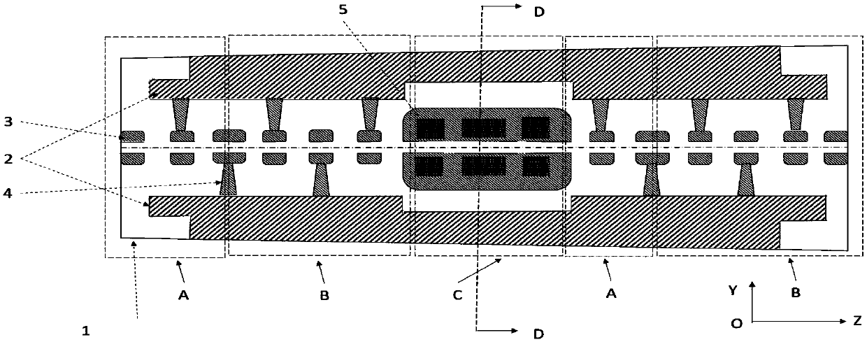
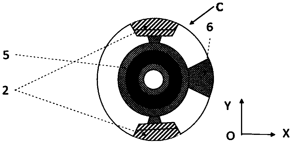
[0033] see image 3 , Figure 4 , a kind of separated focusing type interdigitated longitudinal magnetic mode drift tube linear accelerator of the present embodiment comprises a plurality of drift tubes installed along the central axis of the vacuum radio frequency resonant cavity 1, above and below (or left and right) of the vacuum radio frequency resonant cavity ) is laterally symmetrically provided with a pair of ridge structures 2; the linear accelerator is divided into a longitudinal focusing section A, a 0° accelerating section B, a transverse focusing section C along the forward direction of the incident particle beam, a longitudinal focusing section A, a 0° accelerating section B and a Adjacent drift tubes in the transverse focusing section C (in the figure, the drift tubes in the longitudinal focusing section A and the 0° acceleration section B are denoted by "3", and the drift tubes in the transverse focusing section C are denoted by "30") respectively The support r...

Embodiment 2

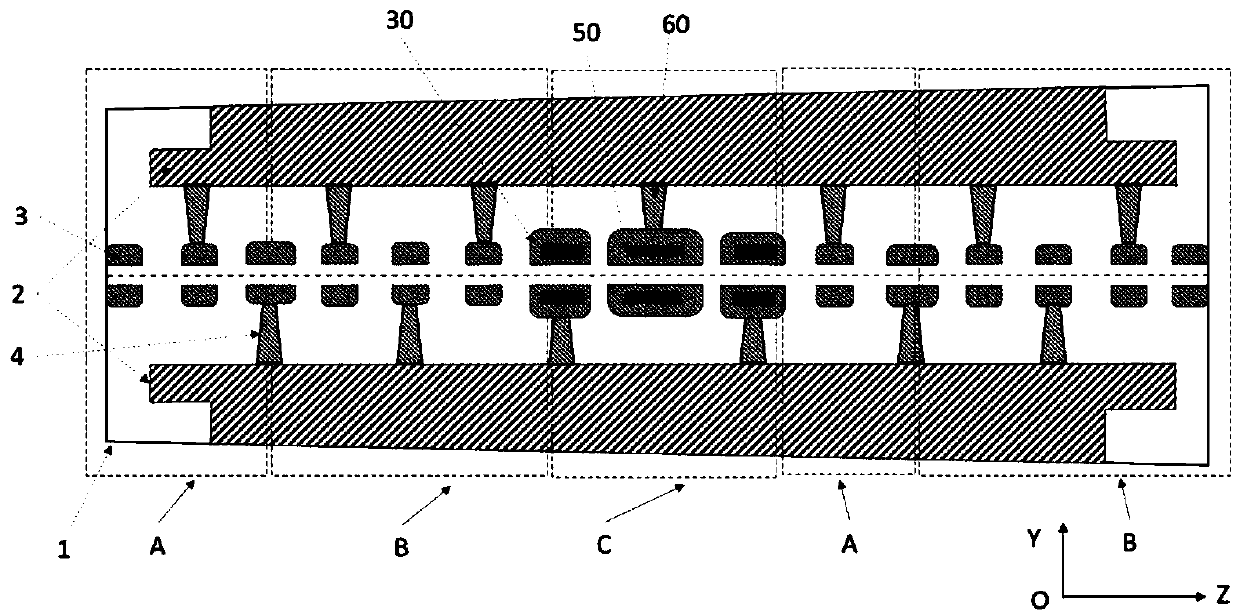
[0051] In this embodiment, on the basis of Embodiment 1, the transverse focusing section C is further improved. In this embodiment, the transverse focusing section C is provided with four drift tubes 30 at intervals, and each drift tube 30 is respectively provided with One permanent magnet quadrupole magnet 50, the magnetic center of each permanent magnet quadrupole magnet 50 coincides with the mechanical center of the drift tube, and the four permanent magnet quadrupole magnets 50 are arranged in the form of focus-divergence-divergence-focus (FDDF), see Figure 7 . Compared with Embodiment 1, this embodiment adopts the FDDF form of focusing structure, and divides the transverse focusing section into four drift tube structures. In this embodiment, the size of the four permanent quadrupole magnets is the same as that of the gradient, and only one A permanent quadrupole magnet is sufficient, and the processing and preparation process of the magnet is simplified under the condit...

Embodiment 3

[0053] In this embodiment, on the basis of Embodiment 2, the transverse focusing section C and the longitudinal focusing section A of the KONUS drift tube linear accelerator are combined, see Figure 8 . The core concept of KONUS drift tube linear accelerator design is segmented, through segmented design, the size of the drift tube in the longitudinal focusing section and 0° acceleration section is small, and the advantage of high shunt impedance of the interdigitated drift tube linear accelerator is maintained. In combination with the split transverse focusing section scheme proposed in Embodiment 2 of the present invention, the synchronous phase of the drift tube gap in the transverse focusing section C is set in the following manner: the longitudinal phase diagram of the bundle in the transverse focusing section C satisfies the following The longitudinal acceptance requirement of the subsequent 0° acceleration section B (the synchronous phase is generally set at about -35°)...


PUM

PropertyMeasurementUnit
Outer diameteraaaaaaaaaa

Abstract

The invention provides an interdigital longitudinal magnetic mode drift tube linear accelerator of a separation focusing type, and belongs to the technical field of linear accelerators. The characteristic of small size of a permanent magnet quadrupole iron is utilized, and a focusing magnet is placed in a single drift tube, so that the shunt impedance and the average acceleration gradient of the acceleration tube can be effectively improved. According to the first drift tube linear accelerator, a plurality of drift tubes are arranged in a transverse focusing section C at intervals, and a permanent-magnet quadrupole magnet is arranged in each drift tube in the axial direction. A drift tube linear accelerator of the other type provided by the invention is an improvement on a first drift tubelinear accelerator, and the synchronous phase of a drift tube gap in a transverse focusing section C is controlled, so that a 0-degree accelerating section B is formed after the transverse focusing section C, thereby saving the length of a longitudinal bunching section A and further improving the accelerating efficiency.

Description

technical field [0001] The invention belongs to the technical field of linear accelerators, and in particular relates to a linear accelerator of a split-focus interdigitated longitudinal magnetic mode drift tube. Background technique [0002] The structure of the drift tube linear accelerator is a vacuum radio frequency resonant cavity with at least two drift tubes (the main body of the drift tube is a hollow cylindrical conductor) installed on the central axis, above and below the vacuum radio frequency resonant cavity (or A pair of ridge structures are arranged symmetrically on the left and right sides, and each drift tube is fixed to the ridge structure of the cavity by a support rod. Its working principle is: feed high-power RF (Radio Frequency, radio frequency) electromagnetic waves with a set frequency into the resonant cavity, and these electromagnetic waves will generate an electric field between the drift tubes, and the hollow cylindrical area inside the drift tube ...

Claims


Application Information

Patent Timeline
IPC IPC(8): H05H9/04
CPCH05H9/042
Inventor 郑曙昕唐若王学武邢庆子马鹏飞雷钰
Owner TSINGHUA UNIV
Why Eureka
Try Eureka