Molding method of aerospace engine nozzle parts

An aerospace engine and molding method technology, applied in the direction of machines/engines, jet propulsion devices, etc., can solve the problems of raw material performance changes, poor product consistency, and easy cracks, so as to achieve no loss of material performance and high stability of production quality , The effect of reducing the amount of machine processing

Active Publication Date: 2020-02-18
BEIJING LANDSPACETECH CO LTD
View PDF5 Cites 0 Cited by
  • Summary
  • Abstract
  • Description
  • Claims
  • Application Information

AI Technical Summary

Problems solved by technology

Among them, the specific method of machining rods, forging rings and flat plates is: take a bar, forging ring, and plate for material reduction processing, obtain the required nozzle parts, and then carry out tailor welding. The disadvantages of this method are: The material utilization rate is low, the amount of machining is huge, and at the same time, it is difficult to process large-sized nozzle parts due to the limitation of the thickness of the material
The specific method of spinning the flat plate and the cylinder is: the forming process of forcibly spinning the flat or barrel-shaped parts onto the mold mold. The disadvantages of this method are: 1. For large diameter and large shaft-to-diameter ratio Parts are difficult to process, and defects such as cracks are prone to be scrapped; 2. The manufacturing process requires a series of spinning tires such as the first pass, the second pass, and the third pass, especially when the diameter is large. The size of the tire will be very large; 3. The spinning process is usually accompanied by heating, heat treatment and other heating processes during hot spinning, which changes the properties of raw materials
The disadvantages of this precaution are: 1. The process is relatively complicated; 2. The requirements for equipment are high, requiring large-scale forming tires and stamping equipment, and welds are prone to problems during the stamping process; 3. The product is deformed and the product consistency is poor; 3. It can only process single-shrinkage or single-expansion structural parts, and it is impossible to obtain parts with both shrinkage and expansion sections at one time

Method used


Image

  • Molding method of aerospace engine nozzle parts
  • Molding method of aerospace engine nozzle parts
  • Molding method of aerospace engine nozzle parts

Examples


Embodiment Construction

[0033] Various exemplary embodiments of the present invention will now be described in detail. The detailed description should not be considered as a limitation of the present invention, but rather as a more detailed description of certain aspects, features and embodiments of the present invention.

[0034] It should be understood that the terminology described in the present invention is only used to describe specific embodiments, and is not used to limit the present invention. In addition, regarding the numerical ranges in the present invention, it should be understood that the upper and lower limits of the range and every intermediate value therebetween are specifically disclosed. Each smaller range between any stated value or intervening value in a stated range and any other stated value or intervening value in a stated range is encompassed within the invention. The upper and lower limits of these smaller ranges may independently be included or excluded from the range.

...


PUM

PropertyMeasurementUnit
widthaaaaaaaaaa
lengthaaaaaaaaaa

Abstract

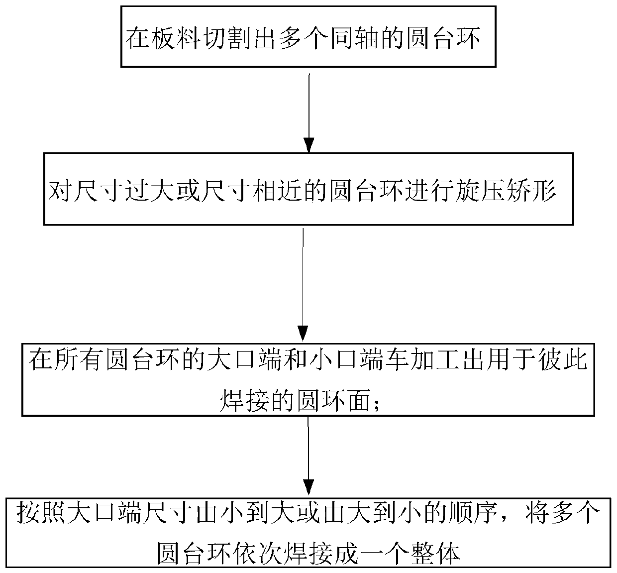
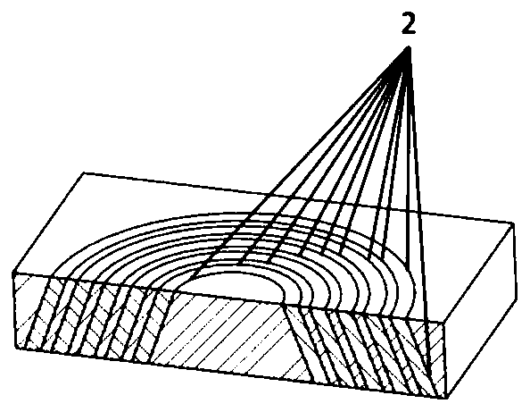
The invention provides a molding method of aerospace engine nozzle parts. The method comprises the following steps: step 1, cutting out a plurality of coaxial conical rings on the plate; Spinning orthopedic; step 3, turning the large mouth end and small mouth end of all the circular table rings to process the torus for mutual welding; step 4, according to the order of the size of the large mouth end from small to large or from large to small, put more The rings are sequentially welded into a whole. The forming method of aerospace engine nozzle parts according to the present invention has the advantages of simple process, not limited by shaft-to-diameter ratio and size, detectable and measurable process, integral molding, high production quality stability, suitable for large-scale automatic production, etc. advantage.

Description

technical field [0001] The invention relates to the field of aerospace engine nozzles, and in particular to a molding method of aerospace engine nozzle parts. Background technique [0002] The thrust chamber is the part responsible for the mixed combustion of fuel in the liquid rocket engine to generate high-temperature and high-pressure gas, which is accelerated and discharged through the throat to obtain reverse thrust. The thrust chamber is generally a Laval profile structure consisting of a cylindrical section, a contracting section and an expanding section. In order to withstand the high temperature of the gas, the nozzle generally adopts regenerative cooling technology, which is composed of the inner wall and the outer wall of the milling groove. At the same time, because the gas temperature is as high as 3500K and the heat exchange power of the wall surface can reach 100 megawatts, the inner wall material of the thrust chamber is mostly made of copper alloy. [0003...

Claims


Application Information

Patent Timeline
Patent Type & Authority Patents(China)
IPC IPC(8): B23P15/00F02K1/00
CPCB23P15/02F02K1/00
Inventor 杨瑞康袁宇宣智超韩建业
Owner BEIJING LANDSPACETECH CO LTD
Why Eureka
Try Eureka