
Oil shale in-situ exploitation downhole ignition and heating device and heating method

An in-situ mining and heating device technology, which is applied in the direction of mining fluid, earthwork drilling, wellbore/well components, etc., can solve the problems of in-situ conversion technology of oil shale, inconvenient installation and operation of equipment and instruments, and low heating efficiency, etc. problems, to achieve the effects of improving combustion efficiency and energy utilization, reducing pipeline transportation loss, and low cost

Active Publication Date: 2019-05-03
JILIN UNIV
View PDF10 Cites 3 Cited by
  • Summary
  • Abstract
  • Description
  • Claims
  • Application Information

AI Technical Summary

Problems solved by technology

[0007] Although the above-mentioned in-situ heating technology does not require the production process of mining oil shale mines from underground to the ground, which reduces the production cost to a certain extent, it still has low heat utilization rate, low heating efficiency, high comprehensive cost, equipment and instrument A series of problems such as inconvenient installation and operation have made many in-situ pyrolysis technologies still in the experimental stage and cannot be realized in field construction.
Therefore, there is an urgent need for a downhole heating device suitable for in-situ mining of oil shale to solve the difficult problem of in-situ conversion of oil shale

Method used


Image

  • Oil shale in-situ exploitation downhole ignition and heating device and heating method
  • Oil shale in-situ exploitation downhole ignition and heating device and heating method

Examples


Embodiment Construction

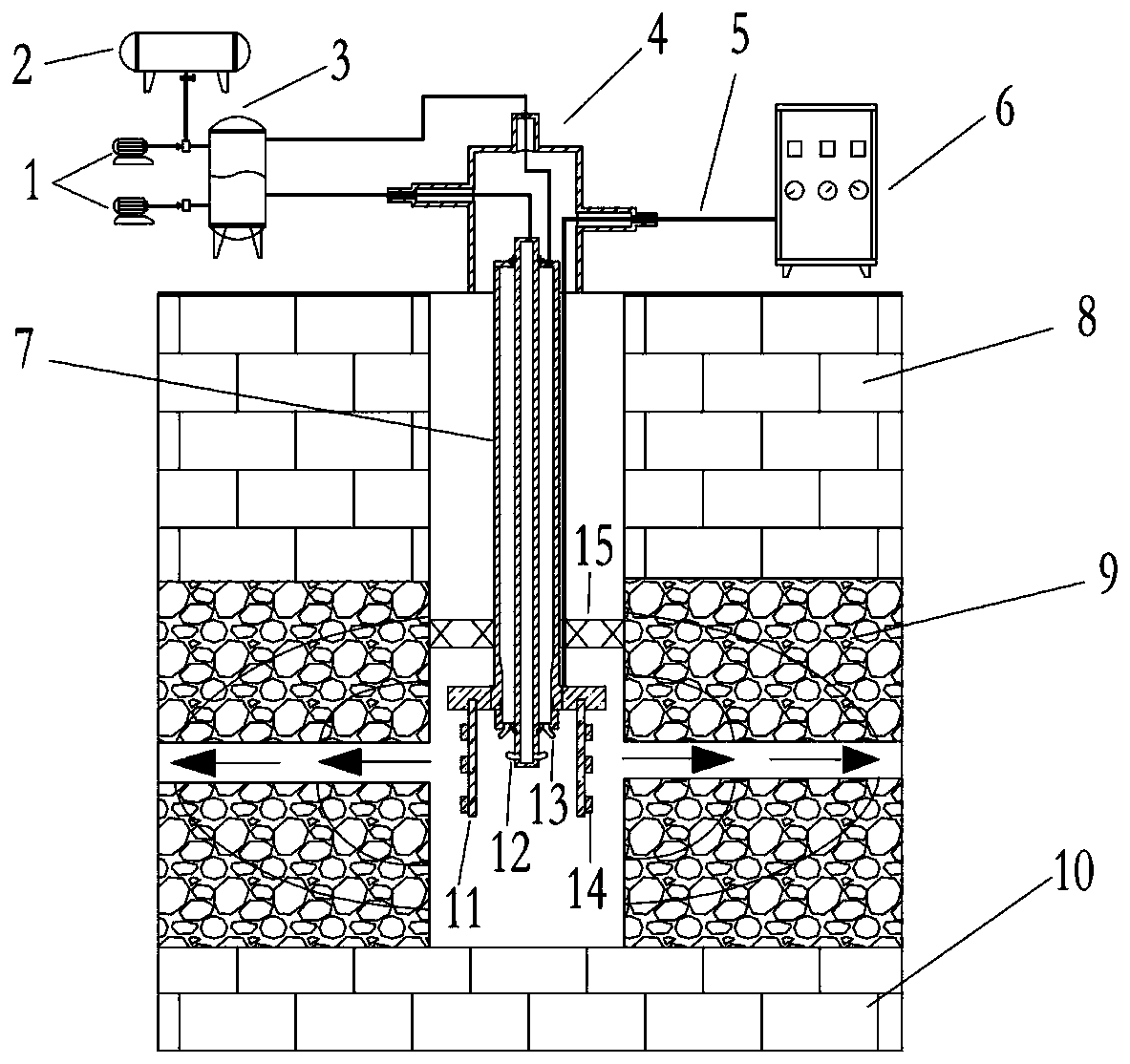
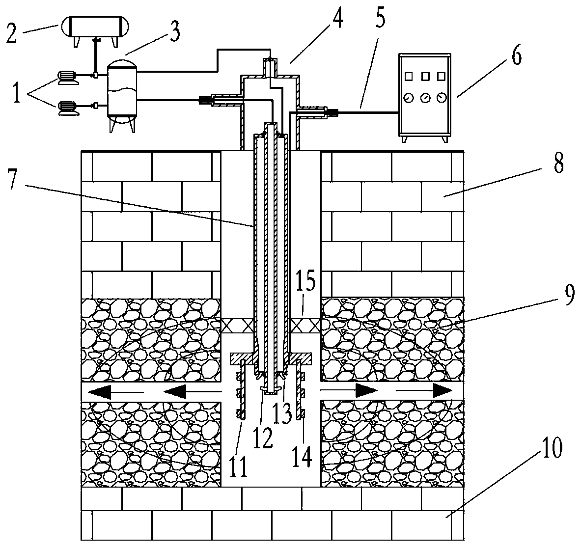
[0028] see figure 1 As shown, the oil shale mining well is an overlying rock layer 8 and an oil shale layer from top to bottom, and the oil shale layer includes a first oil shale layer 9 and a second oil shale layer 10;

[0029] see figure 1 As shown, a downhole ignition and heating device for oil shale in-situ mining, including a motor pump 1, a fuel tank 2, a pressure balance device 3, a wellhead packer 4, a signal cable 5, a heating controller 6, and a double-walled drill pipe 7 , heating rod 11, air nozzle 12, swirl nozzle 13, flame detector 14 and downhole packer 15; motor pump 1 includes air pump and oil pump;

[0030] The motor pump 1, the fuel tank 2 and the pressure balance device 3 form a high-pressure oil and gas injection system;

[0031] The heating controller 6 and the flame detector 14 form an ignition heating measurement and control system;

[0032] The double-walled drill pipe 7, the downhole packer 15 and the signal cable 5 constitute an in-hole pipe strin...


PUM


Abstract

The invention discloses an oil shale in-situ exploitation downhole ignition and heating device and a heating method. The ignition and heating device comprises a high-pressure oil gas injection system,an ignition and heating measurement and control system, a downhole pipe column cable system and a downhole igniting system. When the ignition and heating device operates, firstly, compressed air is injected in a well through a center channel of a dual-wall drill pipe, and high-speed air flow is generated through an air nozzle; and then fuel oil is transported in the well through an annular hollowchannel between the inner wall and the outer wall of the dual-wall drill pipe, the fuel oil is atomized through a swirl nozzle and fully mixed with the high-speed air flow, the fuel oil is ignited under the heating action of a heating rod, and the heat generated by burning is used for heating an oil shale layer. Flame detectors monitor the burning conditions of downhole, a downhole packer enablesthe peak surface of the burning to extend and expand towards the ground layer in the well for heating an oil shale ore deposit. According to the oil shale in-situ exploitation downhole ignition and heating device and the heating method, the loss caused by energy pipeline transportation is reduced, and the burning efficiency of the fuel oil and the utilization ratio of the energy are improved greatly.

Description

technical field [0001] The invention relates to the field of unconventional energy exploitation, in particular to an ignition heating device and heating method for in-situ exploitation of oil shale underground. Background technique [0002] Oil shale, as a new type of energy that can replace conventional oil and gas resources in the 21st century, has always received extensive attention. Oil shale is a kind of sedimentary rock containing organic matter. The content of organic matter usually ranges from 5% to 50%. The main types can be classified into saprophytic, humic or mixed types. Inorganic minerals mainly include quartz, kaolin, clay, carbonate, etc. The organic matter (kerogen) inside it can generate shale oil and pyrolysis gas after high temperature treatment. [0003] At present, the exploitation and utilization of oil shale are mainly divided into two forms, including surface carbonization technology and underground in-situ cracking technology. The development of s...

Claims


Application Information

Patent Timeline
Patent Type & Authority Applications(China)
IPC IPC(8): E21B43/243E21B43/241E21B43/14
CPCY02E10/10
Inventor 郭威杨秦川李强王振东孙友宏邓孙华
Owner JILIN UNIV
Learn More