
Optical fiber ammonia sensor based on Ag-doped ZnO nanoflower and manufacturing method thereof

A technology of ammonia sensor and nanoflower, which is applied in the direction of phase influence characteristic measurement, etc., to achieve the effect of easy manipulation, good ammonia sensing effect and strong repeatability

Active Publication Date: 2019-05-03
HARBIN UNIV OF SCI & TECH
View PDF9 Cites 2 Cited by
  • Summary
  • Abstract
  • Description
  • Claims
  • Application Information

AI Technical Summary

Problems solved by technology

[0004] Aiming at the defects and improvement needs of the prior art, the present invention provides an optical fiber ammonia sensor based on Ag-doped ZnO nanoflowers and a manufacturing method, the purpose of which is to study the interference properties of the optical fiber and design its sensitive components, In this way, the problem of difficult packaging caused by the production of sensor cones can be effectively avoided, and at the same time, the sensitivity of the system can be improved by doping ZnO nanoflowers with Ag elements, so as to prepare high-selectivity and high-sensitivity fiber-optic ammonia. sensor

Method used


Image

  • Optical fiber ammonia sensor based on Ag-doped ZnO nanoflower and manufacturing method thereof
  • Optical fiber ammonia sensor based on Ag-doped ZnO nanoflower and manufacturing method thereof
  • Optical fiber ammonia sensor based on Ag-doped ZnO nanoflower and manufacturing method thereof

Examples


Embodiment Construction

[0028] In order to make the object, technical solution and advantages of the present invention clearer, the present invention will be further described in detail below in conjunction with the accompanying drawings.

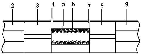
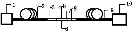
[0029] figure 1 It is a schematic diagram of the overall structure of the fiber optic ammonia sensor based on Ag-doped ZnO nanoflowers according to the present invention. Such as figure 1 The shown optical fiber ammonia sensor based on Ag-doped ZnO nanoflowers constructed according to the present invention mainly includes sequentially connected light source 1, introduction of single-mode optical fiber 2, first thin-core optical fiber 3, gas inlet 4, hollow-core optical fiber 5. Ag-doped ZnO nanoflower layer 6, gas outlet 7, second thin-core optical fiber 8, leading single-mode optical fiber 9 and spectrometer 10. Wherein the light source 1 is a broadband light source with a central wavelength of 1550nm, which is used to generate optical signals; the single-mode ...


PUM

PropertyMeasurementUnit
Diameteraaaaaaaaaa
Lengthaaaaaaaaaa
Lengthaaaaaaaaaa

Abstract

The invention discloses an optical fiber ammonia sensor based on the Ag-doped ZnO nanoflower. The optical fiber ammonia sensor includes a light source, a lead-in single mode fiber, a first fine core fiber, a hollow core fiber, an Ag-doped ZnO nanoflower layer, a second fine core fiber, a lead-out single mode fiber and a spectrometer which are sequentially connected, wherein the center wavelength of the broadband light source is 1550 nm, the light is transmitted to the first fine core fiber through the lead-in single mode fiber, alignment and welding with the lead-in single mode fiber are performed to generate interference, a signal mode is coupled with the hollow core fiber, the diameter of the hollow core fiber is 125mum, the fiber core is 14.2 mum, the internal part is the Ag-doped ZnO nanoflower layer, two ends are aligned and welded with the first fine core fiber and the second fine core fiber, an interference signal is led out through the lead-out single mode fiber, two holes aremade on the surface and are an air inlet and an air outlet respectively for ammonia transmission, and the spectrometer detects the transmission spectrum in an interference mode to obtain sensory data.The invention discloses a corresponding making method. The optical fiber ammonia sensor is advantaged in that through increasing the indirect contact area with ammonia by means of the ZnO nanoflower,sensitivity of the system can be significantly increased.

Description

technical field [0001] The invention belongs to the technical field of optical fiber sensors, and more specifically relates to an optical fiber ammonia sensor based on Ag-doped ZnO nanoflowers and a manufacturing method. Background technique [0002] Ammonia is a harmful, colorless, irritating and toxic gas that contributes to climate change and the destruction of the ozone layer. Therefore, there is an urgent need for optical fiber sensors with high sensitivity, high selectivity and simple preparation. Optical fiber sensors based on evanescent field type have always been concerned by researchers because of their small size, anti-electromagnetic interference, high temperature resistance, and corrosion resistance. However, at present, for optical fiber sensors based on evanescent fields, there is still the problem of low sensitivity, and there are strict requirements for the preparation technology of micro-nano fibers, otherwise it is difficult to prepare micro-nano fibers w...

Claims


Application Information

Patent Timeline
IPC IPC(8): G01N21/45
Inventor 沈涛夏振涛冯月李晓晓
Owner HARBIN UNIV OF SCI & TECH
Learn More