
A CMOS relaxation oscillator circuit with a temperature compensation function

A relaxation oscillator and temperature compensation technology, applied in the field of relaxation oscillator circuits and oscillator circuits, can solve the problems that hinder the trend of node miniaturization, and achieve the advantages of reducing leakage current, small circuit size, temperature compensation and power supply sensitivity Effect

Pending Publication Date: 2019-05-03
湘潭芯力特电子科技有限公司
View PDF10 Cites 2 Cited by
  • Summary
  • Abstract
  • Description
  • Claims
  • Application Information

AI Technical Summary

Problems solved by technology

[0003] Crystal oscillators are commonly used in wireless sensor networks (WSNs) due to their good suppression of PVT variations, but the size of crystal oscillators is a huge obstacle hindering the trend of node miniaturization, and the frequency of crystal oscillators is robust performance at the expense of power consumption

Method used


Image

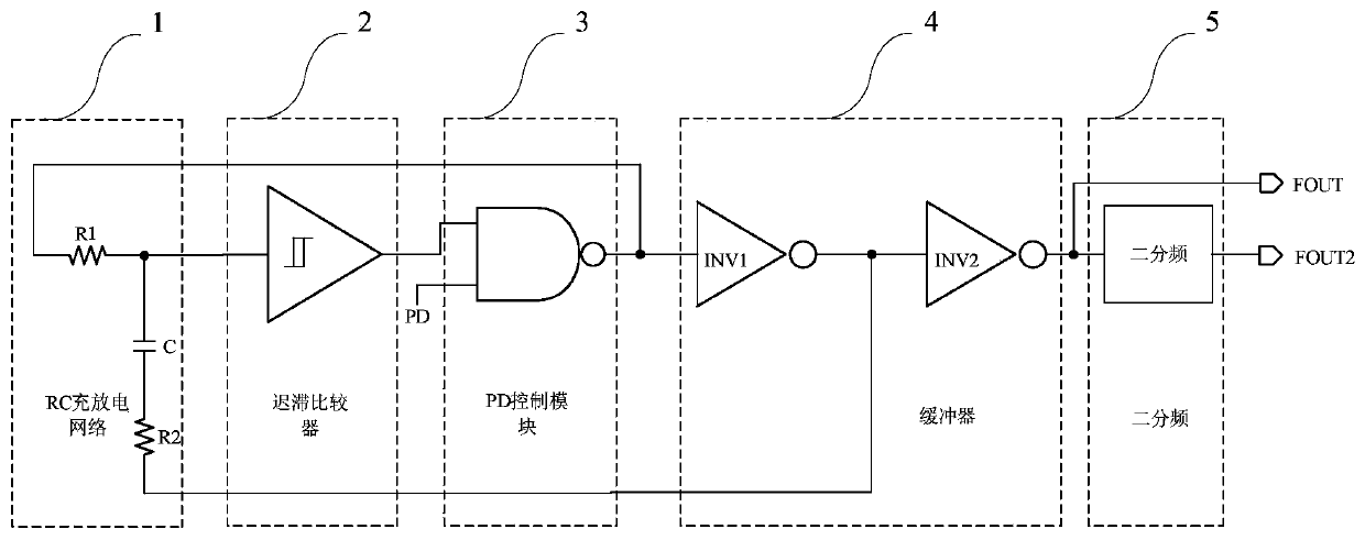
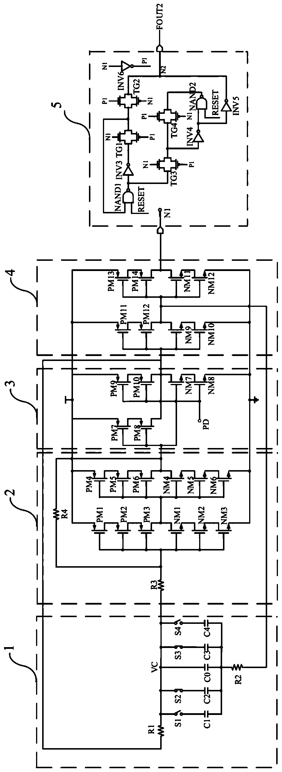
  • A CMOS relaxation oscillator circuit with a temperature compensation function
  • A CMOS relaxation oscillator circuit with a temperature compensation function
  • A CMOS relaxation oscillator circuit with a temperature compensation function

Examples


Embodiment Construction

[0018] In order to make the purpose, technical solution and advantages of the present invention clearer, the embodiments of the present invention will be described in detail below in conjunction with the accompanying drawings.

[0019] A temperature-compensated CMOS relaxation oscillator circuit in this embodiment, its overall frame diagram is as follows figure 1 As shown, it includes RC charging and discharging network 1, hysteresis comparator 2, PD control module 3, buffer 4, and divide-by-two 5; wherein, the RC charging and discharging network includes first resistor R1, second resistor R2, capacitor C, buffer The device 4 includes a first inverter INV1 and a second inverter INV2; one end of the first resistor R1 is connected to the output end of the PD control module 3 and the input end of the buffer 4, and the other end of the first resistor R1 is connected to the capacitor C. The input end of the hysteresis comparator 2 is connected, one end of the second resistor R2 is ...


PUM


Abstract

The invention discloses a CMOS relaxation oscillator circuit with a temperature compensation function. The CMOS relaxation oscillator circuit comprises an RC charging and discharging network, a hysteresis comparator, a PD control module, a buffer and a two-divided frequency; The RC charging and discharging network comprises a first resistor, a second resistor and a capacitor. The buffer comprisesa first phase inverter and a second phase inverter. Wherein one end of the first resistor is connected with the output end of the PD control module and the input end of the buffer, the other end of the first resistor is connected with the capacitor and the input end of the hysteresis comparator, one end of the second resistor is connected with the capacitor, and the other end of the second resistor is connected with the output end of the first inverter, the input end of the second inverter and the input end of the two-section frequency converter; The output end of the hysteresis comparator isconnected with the first input end of the PD control module; The output end of the PD control module is connected with the input end of the buffer, and the second input end of the PD control module isconnected with an external control signal PD; And the output end of the buffer is connected with the input end of the two-way frequency divider. The temperature compensation and the power supply sensitivity are improved, and the leakage current when the circuit is turned off is reduced.

Description

technical field [0001] The invention relates to an oscillator circuit, in particular to a relaxation oscillator circuit with a stable output frequency within a certain temperature range, which belongs to the field of integrated circuits. Background technique [0002] Oscillators are widely used in integrated circuits to provide clock signals and other purposes. Some applications require the oscillator to be stable within a large temperature change, and at the same time have strict requirements on power consumption and area. For example, in wireless sensor networks (WSNs), each node is composed of centimeter-scale or even millimeter-scale devices, and these tiny devices will provide ubiquitous sensor platforms for environmental, biomedical, military, and industrial applications. Power consumption, size, and frequency stability of wireless communication clocks are major concerns for millimeter-scale wireless sensor networks (WSNs). [0003] Crystal oscillators are commonly us...

Claims


Application Information

Patent Timeline
IPC IPC(8): H03K3/011H03K3/012
Inventor 谢亮吴唐政张文杰金湘亮
Owner 湘潭芯力特电子科技有限公司
Learn More