Optical wavelength conversion component and light emitting device

A light wavelength conversion and component technology, applied in the direction of luminescent materials, filters, electrical components, etc., can solve the problems of increased transmission, uneven color, decreased durability, etc., and achieve the effect of sufficient fluorescence intensity

Active Publication Date: 2021-07-20
NGK SPARK PLUG CO LTD
View PDF7 Cites 0 Cited by
  • Summary
  • Abstract
  • Description
  • Claims
  • Application Information

AI Technical Summary

Problems solved by technology

For example, in Patent Document 1, the amount of YAG:Ce is set at 22 to 55 vol% of the whole. When it is less than 22 vol%, the transmission of blue light increases, causing color unevenness. When it is more than 55 vol%, the thermal conductivity decreases. Decreased durability

Method used


Image

  • Optical wavelength conversion component and light emitting device
  • Optical wavelength conversion component and light emitting device
  • Optical wavelength conversion component and light emitting device

Examples


Embodiment approach

[0049] [1-1. Structure of Optical Wavelength Converter]

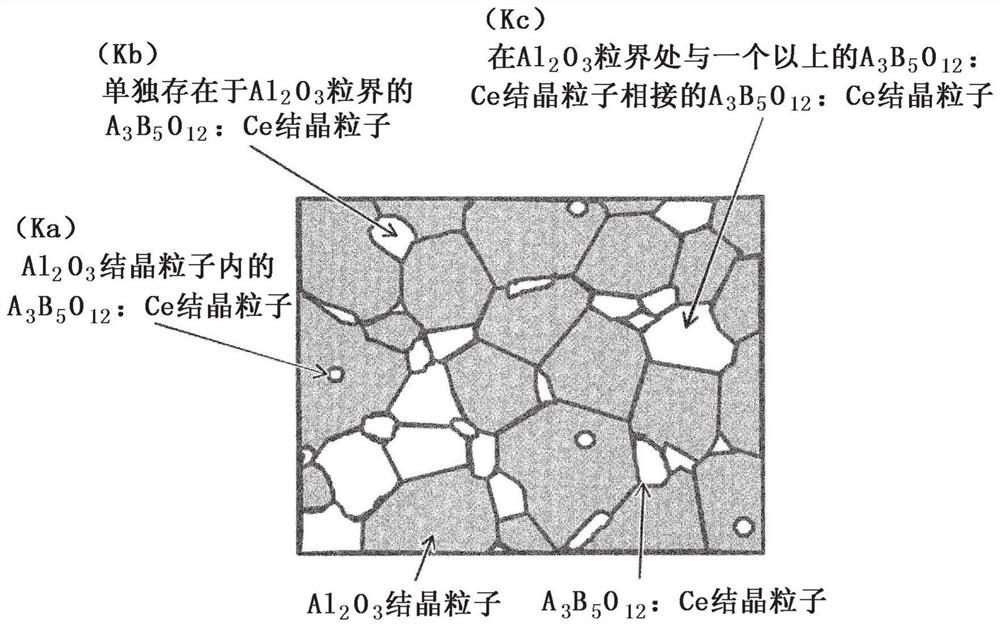
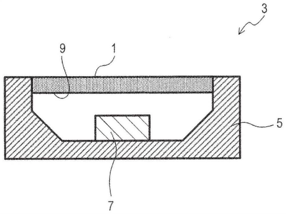
[0050] First, the optical wavelength conversion member of the embodiment will be described. Such as figure 1 As shown, the optical wavelength conversion component 1 of the embodiment (refer to figure 2 ) is, for example, a plate-shaped ceramic sintered body, composed of Al 2 o 3 Crystalline particles and by formula A 3 B 5 o 12 : Crystal particles of a component represented by Ce (hereinafter sometimes referred to as A 3 B 5 o 12 : Ce crystal particles) are composed of polycrystalline bodies as the main component.

[0051] In this optical wavelength conversion component 1, A 3 B 5 o 12 A and B in are at least one element selected from the following element groups:

[0052] A: Sc, Y, lanthanides other than Ce

[0053] B: Al, Ga.

[0054] Furthermore, A of the range of 20 μm square of the cross section of the ceramic sintered body 3 B 5 o 12 : Among the N Ce crystal particles, there will be Al 2 o 3 T...

Embodiment 1

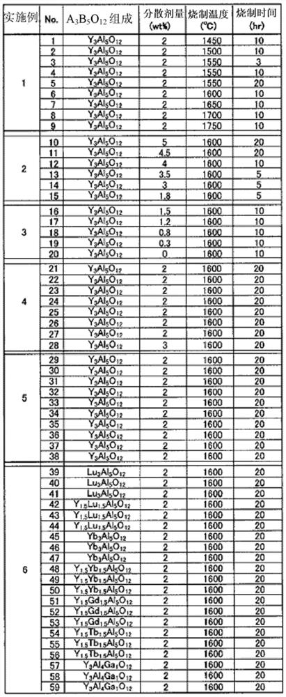
[0076] According to the conditions shown in Table 1 and Table 2 below, samples of ceramic sintered bodies of Nos. 1 to 9 were produced. In addition, No. 1-9 among each sample is a sample within the range of this invention.

[0077]Specifically, for each sample, the YAG (Y 3 Al 5 o 12 ) to 21 vol%, and Al was weighed so that the Ce concentration was 1 mol% relative to Y in YAG. 2 o 3 (average particle size 0.3μm), Y 2 o 3 (average particle size 1.2μm), CeO 2 (average particle size 1.5 μm).

[0078] This was put into a ball mill together with pure water and a predetermined amount of dispersant (2% by weight in terms of solid matter relative to the raw material powder), and pulverized and mixed for 12 hours. The obtained slurry was dried and granulated, and the granulated product was used to produce a molded body. Then, the molded body was fired in the atmosphere under normal pressure at a firing temperature of 1450° C. to 1750° C. and a holding time of 3 to 20 hours. T...

Embodiment 2

[0102] By the same manufacturing method as in Example 1, as shown in Table 1 and Table 2 below, samples of ceramic sintered bodies (samples of Nos. 10 to 15) were prepared, and evaluated in the same manner.

[0103] However, at the time of preparation, the dispersant amount was varied within the range of 1.8 to 5 wt%, and the firing time was varied within the range of 5 to 20 hours. In addition, among each sample, No. 11-14 is a sample within the range of this invention, No. 10, 15 is a sample outside the range of this invention (comparative example).

[0104] As a result, in any of the samples, the relative density was 99% or more, and they were sufficiently densified. And it can be seen that, except for No.10, Al 2 o 3 The average crystal grain size is in the range of 0.3-10μm, A 3 B 5 o 12 : Ce (YAG: Ce) has an average crystal grain size in the range of 0.3 to 5 μm. Furthermore, as can be seen from Table 2 below, Nos. 11 to 14 in which X, Y, and Z were within the rang...


PUM


Abstract

The present invention provides a light wavelength conversion member and a light emitting device capable of achieving both high fluorescence intensity and high color uniformity. In the optical wavelength conversion part (1), A 3 B 5 o 12 A and B in are at least one element selected from the following element groups, A: Sc, Y, lanthanide elements other than Ce, B: Al, Ga, and the 20 μm square of the cross section of the ceramic sintered body A in the range 3 B 5 o 12 : Among the N Ce crystal particles, Al exists 2 o 3 The number of crystal particles is a, and the other A 3 B 5 o 12 : Ce crystal particles exist in Al without contact 2 o 3 The number of crystal grain boundaries is b, and one or more other A 3 B 5 o 12 : Ce crystal grains contact and exist in Al 2 o 3 The number of crystal grain boundaries is c, and when the ratios a / N, b / N, and c / N of each number to the whole are X, Y, and Z respectively, each ratio satisfies the following range: 0%≤X≤25 %, 9%≤Y≤45%, 48%≤Z≤90%.

Description

technical field [0001] The present invention relates to an optical wavelength conversion member capable of converting the wavelength of light, and a light emitting device including the optical wavelength conversion member. Background technique [0002] Conventionally, in white lighting equipment using light-emitting diodes (LED: Light Emitting Diode) and semiconductor lasers (LD: Laser Diode) as light sources, blue LEDs and blue LDs are combined with yellow phosphors that are complementary colors to blue. Get white lighting going mainstream. [0003] Resin-based, glass-based, and ceramic-based materials are known as the material of the phosphor. However, in recent years, due to the increase in the output of light sources, the temperature of phosphors tends to increase, and the development of ceramic-based phosphors with high durability has been progressing. . [0004] For example, as the ceramic-based phosphor, the chemical formula A 3 B 5 o 12 Represents the garnet-typ...

Claims


Application Information

Patent Timeline
Patent Type & Authority Patents(China)
IPC IPC(8): G02B5/20C04B35/50C09K11/80H01L33/50
CPCH01L33/502H01L33/505H01L33/507C09K11/7774C04B35/117C04B35/44C04B2235/3224C04B2235/3222C04B2235/3229C04B2235/3225C04B2235/3217C04B2235/96C04B2235/785C04B2235/786C04B2235/9646C04B2235/6567C04B2235/5445C04B2235/5436C04B2235/9661C04B35/50C09K11/64G02B5/20H01L33/16C09K11/7721C09K11/62C04B35/115H01L33/501H01L33/504H01L33/50
Inventor 茂木淳高久翔平胜祐介光冈健伊藤经之
Owner NGK SPARK PLUG CO LTD
Why Eureka
Try Eureka