Absolute linear displacement sensor based on decimal shift coding

A linear displacement and decimal system technology, which is applied in the direction of instruments, measuring devices, optical devices, etc., can solve the problems that the sensor is not easy to miniaturize and the method is complicated

Active Publication Date: 2019-05-07
CHONGQING UNIV OF TECH
View PDF9 Cites 5 Cited by
  • Summary
  • Abstract
  • Description
  • Claims
  • Application Information

AI Technical Summary

Problems solved by technology

Gray code is the most widely used code in absolute photoelectric encoders. It is obtained by bit-by-bit XOR of natural binary codes. There is only one bit change between any adjacent codes. Higher, but due to its coding characteristics, when the number of digits increases, the number of corresponding code channels increases, making it difficult to miniaturize sensors using Gray codes
The distance code code is composed of distance code reference marks at different distances. Its advantage is that the engraving is simple, and there is only one code track except the incremental code track. The disadvantage is that it needs to move a small distance before use to determine the absolute position.
On the more miniaturized sensors, single-track absolute encoding is also used. This encoding only uses one code track, so its volume is smaller, but the way to construct the encoding is more complicated, especially the absolute position of the high-order word length. coding

Method used


Image

  • Absolute linear displacement sensor based on decimal shift coding
  • Absolute linear displacement sensor based on decimal shift coding
  • Absolute linear displacement sensor based on decimal shift coding

Examples


Embodiment 1

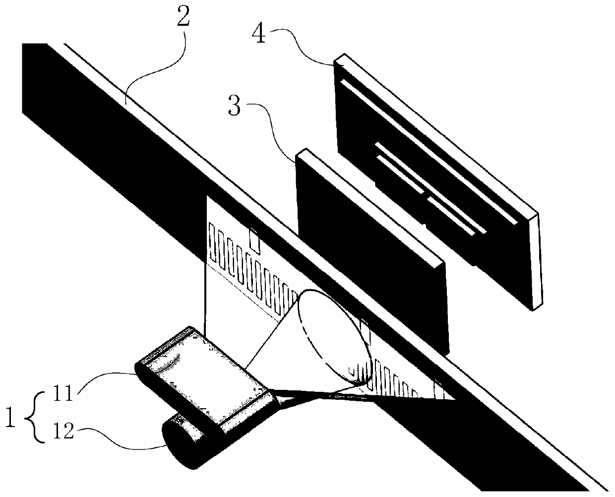
[0032] Embodiment 1: as Figure 1 to Figure 6 The shown absolute linear displacement sensor based on decimal displacement coding includes a light emitting element 1, a moving scale base 2, a fixed scale base 3, a photodetector 4 and a signal processing circuit.

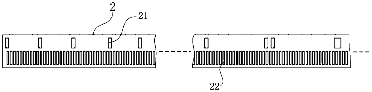
[0033] The moving scale base 2 uses glass as the base material, and covers its upper surface with a light-shielding material, so that a row of rectangular light-transmitting surfaces I that are not covered with light-shielding materials and are evenly spaced at 0.3mm along the measuring direction are left on the moving scale base 2, forming an incremental At the same time, a row of rectangular light-transmitting surfaces II that are not covered with light-shielding materials and distributed along the measurement direction in the order of decimal shift coding are left on the moving scale base 2 to form an absolute code track 21, and the incremental code track 22 is located at Below the absolute code track 21, the width...

Embodiment 2

[0051] Embodiment 2: as Figure 8 The shown absolute linear displacement sensor based on decimal shift coding has the same measurement principle as that of Embodiment 1, and most of its structure is the same as that of Embodiment 1. The difference is that in this embodiment, the light-emitting element 1 is a single Semiconductor surface light source (that is, only composed of semiconductor surface light source), the semiconductor surface light source adopts a surface-shaped light-emitting diode, driven by a sinusoidal alternating current signal superimposed with a DC bias, and the emitted light forms an alternating light intensity. The illumination area acts on the incremental code track 22 and the absolute code track 21. The length of the light intensity alternating illumination area formed on the absolute code track 21 is 14mm, and the light intensity alternating light area formed on the incremental code track 22 is The length of the illuminated area is 7mm.

Embodiment 3

[0052] Embodiment 3: as Figure 9 to Figure 12 The shown absolute linear displacement sensor based on decimal shift coding has the same measurement principle as that of Embodiment 1, and most of its structure is the same as that of Embodiment 1, except that:

[0053] In this embodiment, the light-emitting element 1 is a single semiconductor surface light source (that is, only composed of a semiconductor surface light source). driving, the emitted light forms an alternating light intensity area, which acts on the incremental code track 22 and the absolute code track 21, and the length of the light intensity alternating light area formed on the absolute code track 21 is 14mm, and the incremental The length of the illuminated area with alternating light intensity formed on the code track 22 is 7mm.

[0054] In this embodiment, there are two rows of rectangular light-transmitting surfaces I that are not covered with light-shielding materials and are evenly spaced by 0.3mm along t...


PUM


Abstract

The invention discloses an absolute linear displacement sensor based on decimal shift coding. The absolute linear displacement sensor based on decimal shift coding comprises a light emitting component, a movable ruler base, a fixed ruler base, a photoelectric detector and a signal processing circuit; an absolute code channel and an incremental code channel are on the movable ruler base; decimal shift codes are engraved on the absolute code channel; uniformly distributed rectangular light transmission surfaces I are engraved on the incremental code channel; light emitted by the light emitting component can form a light intensity alternative illumination area acting on the absolute code channel and the incremental code channel; a long strip-shaped light transmission surface and four sets oflight transmission surfaces are on the fixed ruler base, and arranged according to a specific space position; after an electric signal reflecting the absolute position output by the photoelectric measuring head of the photoelectric detector is processed, an absolute position value is obtained; after four light current signals reflecting incremental displacement are processed, an incremental displacement value is obtained; and the absolute position value is added with the incremental displacement value, so that an absolute linear displacement value is obtained. According to the absolute lineardisplacement sensor based on decimal shift coding disclosed by the invention, the absolute linear displacement can be precisely measured; the graph coding difficulty can be reduced; and the measurement reliability can be improved.

Description

technical field [0001] The invention belongs to the field of precision linear displacement measurement, in particular to an absolute linear displacement sensor based on decimal displacement coding. Background technique [0002] The traditional precision linear displacement measurement is mainly grid sensors, typically represented by grid sensors such as gratings, magnetic grids, and capacitive grids. Their common characteristics are that the grid lines that are evenly spaced are used as the measurement reference. In order to improve the measurement accuracy and resolution, these gate sensors use precision scribe lines and need to rely on high-precision electronic subdivision technology, complex and harsh scribe line process and electronic subdivision circuit cause high cost of the sensor and poor anti-interference ability. [0003] In the field of precision linear displacement measurement, in recent years, a time grating sensor with clock pulse as the reference for displacem...

Claims


Application Information

Patent Timeline
Patent Type & Authority Applications(China)
IPC IPC(8): G01B11/02
Inventor 付敏朱革冯济琴余小雨张双亚
Owner CHONGQING UNIV OF TECH
Why Eureka
Try Eureka