Method for enhancing performance of ECR (Electron Cyclotron Resonance) plasma source

A plasma source and plasma technology, applied in the field of ion source applications, can solve problems such as low beam density and insufficient performance parameters, and achieve the effect of enhancing ionization efficiency and improving plasma performance

Inactive Publication Date: 2019-05-07
BEIJING UNIV OF TECH
View PDF5 Cites 4 Cited by
  • Summary
  • Abstract
  • Description
  • Claims
  • Application Information

AI Technical Summary

Problems solved by technology

In some application fields that require strong plasma beam current, the performance parameters of the current ECR plasma source are slightly insuff

Method used


Image

  • Method for enhancing performance of ECR (Electron Cyclotron Resonance) plasma source

Examples


Embodiment 1

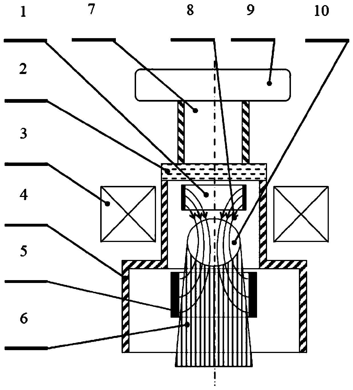
[0020] On the basis of the existing ECR plasma source, the additional hot cathode 5 is made of tungsten wire, made into a solenoid shape, and placed above the resonance area. The anode 1 is made of molybdenum sheet, made into a cylindrical shape, and placed close to the lower edge of the resonance area. A voltage of 100V is applied between the cathode and the anode, and the hot cathode 5 is heated to the common electron emission temperature of tungsten, 2400°C, by means of self-electric heating, and a gas of 50Pa is introduced into the vacuum chamber. The highest plasma beam density that can be achieved by this ECR plasma source is 5×10 21 / m 2

Embodiment 2

[0022] On the basis of the existing ECR plasma source, the additional hot cathode 5 is made of lanthanum hexaboride, made into a cylindrical shape, and placed under the resonance area. The anode 1 copper plate is made into the same shape as the section of the waveguide and placed above the resonance area. A voltage of 200V is applied between the cathode and the anode, and the hot cathode 5 is heated to the common electron emission temperature of lanthanum hexaboride, which is 1500°C, by means of infrared baking heating, and a gas of 1.0Pa is introduced into the vacuum chamber. The highest plasma beam density that can be achieved by this ECR plasma source is 2×10 22 / m 2

Embodiment 3

[0024] On the basis of the existing ECR plasma source, the additional hot cathode 5 is made of a rare earth tungsten alloy sheet, made into a cylindrical shape, and placed close to the lower edge of the resonance area. The anode 1 is made of a stainless steel sheet, made into a cylindrical shape, and placed on the upper edge of the resonance area. A voltage of 20V is applied between the cathode and the anode, and the hot cathode 5 is heated to the common electron emission temperature of rare earth tungsten at 2000°C by means of high-frequency heating, and a gas of 0.01Pa is introduced into the vacuum chamber. The highest plasma beam density achievable by this ECR plasma source is 8×10 21 / m 2 .


PUM


Abstract

The invention relates to a method for enhancing the performance of an ECR (Electron Cyclotron Resonance) plasma source, and belongs to the application field of a low-temperature plasma source. The principle of the invention lies in that the original source of space electrons is a small quantity of free electrons in a resonance region of the existing ECR, electrons generated by gas ionization are source of the electrons when plasma discharge is formed, the electron density is limited when equilibrium is achieved, and the improvement of plasma parameters is restricted. On the basis of the existing ECR plasma source, a method of injecting electrons into the resonance region space in a compulsive and active manner is adopted. On the basis of the existing electron source, a lot of thermal electrons are generated by using a thermionic cathode, and the thermal electrons enter the resonance space under the control of an electric field passing through the resonance region, so that the electrondensity of the resonance region is greatly improved. Since the electron density of the resonance region is greatly improved, the ECR ionization efficiency is further enhanced, and the performance indexes such as the beam density of the ECR plasma source are improved.

Description

technical field [0001] The invention belongs to the application field of low-temperature plasma sources, and relates to a method for improving plasma parameters by actively injecting electrons into electron cyclotron resonance (hereinafter referred to as ECR) space, and the invention is applicable to ECR plasma sources. Background technique [0002] The ECR plasma source is suitable for material preparation and surface treatment, and has a wide range of applications. Higher plasma parameters can further enhance its performance and application range. [0003] When the ECR plasma source is running, it is necessary for the microwave to reach the resonant magnetic field area in the vacuum chamber smoothly, so that the electrons in the resonant area can generate cyclotron resonance and form plasma. In some application fields that require a strong plasma beam, the performance parameters of the current ECR plasma source are slightly insufficient. For example, when it is used to stu...

Claims


Application Information

Patent Timeline
IPC IPC(8): H05H1/46
CPCH05H1/46
Inventor 王波张天一吕广宏
Owner BEIJING UNIV OF TECH
Why Eureka
Try Eureka