
In-situ reduction system for gas-phase pollutants at refuse landfill based on intercalation function layer

A landfill and functional layer technology, which is applied in the construction of intercalated functional layers in landfills, in-situ reduction of methane, malodorous gases, and in-situ reduction systems for gas phase pollutants in landfills, can solve the problem of Increase the cost of raw materials, the air is not easy to enter the interior of the garbage dump, etc., to achieve the effect of rich pore structure, long service life, and accelerated activities

Active Publication Date: 2019-05-10
SHANGHAI JIAO TONG UNIV
View PDF7 Cites 2 Cited by
  • Summary
  • Abstract
  • Description
  • Claims
  • Application Information

AI Technical Summary

Problems solved by technology

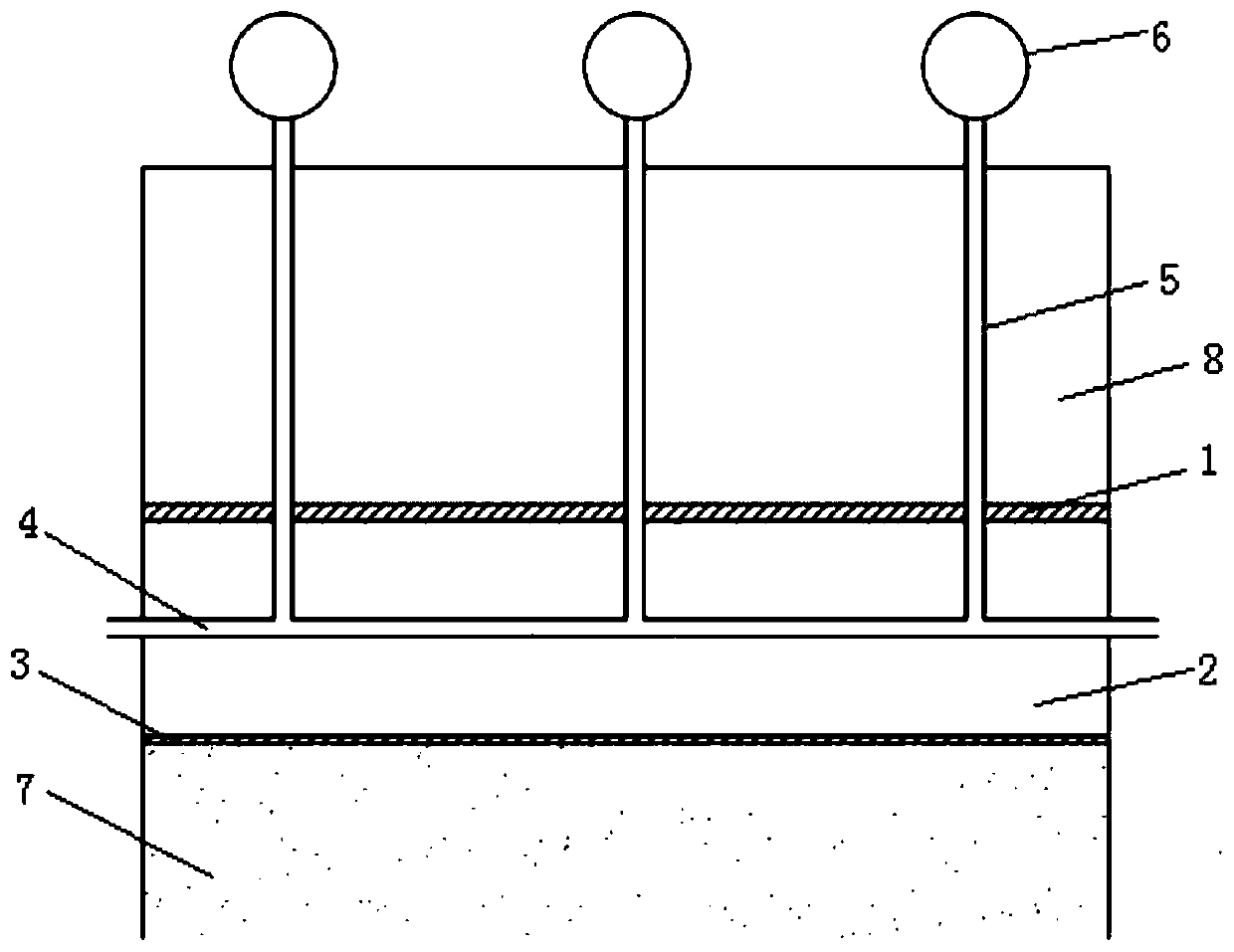
[0003] Comparing Zhao Youcai and Han Dan's "system and method for oxidizing methane (CN 102906032 A)" patent, this patent makes full use of the methane oxidation ability of mineralized waste, introduces external gas through pipelines, creates an aerobic environment, and The nutrient solution improves the methane oxidation rate of the landfill and provides a suitable landfill methane oxidation method; however, due to the need to add the nutrient solution, the cost of raw materials is increased, and at the same time only relying on the natural flow of external gas, the air is not easy to enter the garbage dump The interior of the body, especially the implementation process is exposed to the surface, which can easily lead to the release of odor

Method used


Image

  • In-situ reduction system for gas-phase pollutants at refuse landfill based on intercalation function layer
  • In-situ reduction system for gas-phase pollutants at refuse landfill based on intercalation function layer

Examples


Embodiment 1

[0035] Example 1. Construction of a new type of landfill intercalation functional layer in-situ deodorization system

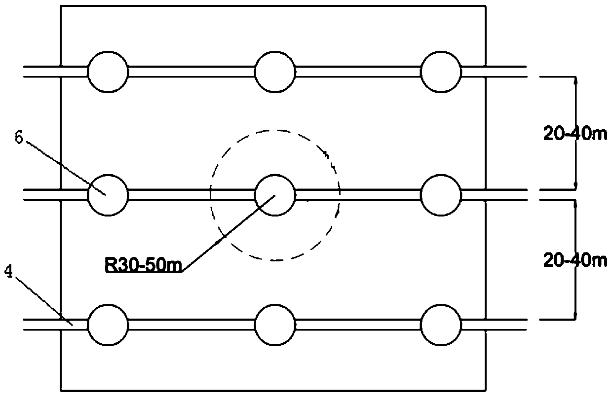
[0036] An in-situ reduction system for gaseous pollutants in landfills, such as figure 1 and figure 2 As shown, the intercalation type functional layer is included above the garbage dump body 7 of the landfill and below the closure covering system 8 . The intercalated functional layer includes a non-woven breathable film layer 3, a functional packing layer 2 and a HDPE film layer 1 arranged in sequence, and a non-powered automatic air exchange system is also arranged in the functional packing layer 2.

[0037] The preparation of the functional filler layer 2: First, take the garbage from the Laogang landfill for about 8-12 years, and after roughly sieving, the particle size is 6 -1×10 7 pieces / g of mineralized waste; the sludge charcoal is directly fired from the remaining sludge from the sewage plant at 500°C under anaerobic conditions; then the fired slud...

Embodiment 2

[0041] Example 2. Construction of a new type of landfill intercalation functional layer in-situ deodorization system

[0042] An in-situ reduction system for gaseous pollutants in a landfill site, comprising setting an intercalation-type functional layer above the garbage pile of the landfill site and below the closure covering system. The intercalated functional layer includes a non-woven breathable film layer, a functional packing layer and an HDPE film layer arranged in sequence, and a non-powered automatic air exchange system is also arranged in the functional packing layer.

[0043] The preparation of the functional packing layer: Firstly, the garbage from the Laogang landfill for about 8-12 years is taken, and after roughly screening, the particle size is 6 -1×10 7 pieces / g of mineralized waste; the sludge charcoal is directly fired from the remaining sludge from the sewage plant at 400°C under anaerobic conditions; then the fired sludge charcoal is buried in the mineral...

Embodiment 3

[0047] Example 3. Construction of a new landfill intercalation functional layer in-situ deodorization system

[0048] An in-situ reduction system for gaseous pollutants in a landfill site, comprising setting an intercalation-type functional layer above the garbage pile of the landfill site and below the closure covering system. The intercalated functional layer includes a non-woven breathable film layer, a functional packing layer and an HDPE film layer arranged in sequence, and a non-powered automatic air exchange system is also arranged in the functional packing layer.

[0049] The preparation of the functional packing layer: Firstly, the garbage from the Laogang landfill for about 8-12 years is taken, and after roughly screening, the particle size is 6 -1×10 7 pieces / g of mineralized waste; the sludge charcoal is directly fired from the remaining sludge from the sewage plant at 300°C under anaerobic conditions; then the fired sludge charcoal is buried in the mineralized was...


PUM


Abstract

The invention discloses an in-situ reduction system for gas-phase pollutants at a refuse landfill based on an intercalation function layer. The system comprises the intercalation function layer disposed above a refuse heap body of the refuse landfill and under a closure covering system, wherein the intercalation function layer comprises a gas-permeable film layer, functional filling layer and an HDPE film layer which are disposed in succession; and a power-free air automatic exchange system is also disposed in the functional filling layer. Mineralized refuses in the functional filling layer are characterized by a high organic content, a large number of microbe, abundant porous structures of mud carbon, a high content of nitrogen in straw stalks after oxidative ammonolysis and so forth andthe power-free air automatic exchange system is installed to promote formation of an aerobic environment for microbial activities, so the system can effectively reduce a release concentration and a release amount of the gas-phase pollutants at the refuse landfill. Application of the system in a current refuse landfill structure has the advantages that operations are simple; cost is low; adsorptionand degradation effects are good; and social and economic benefits are very high.

Description

technical field [0001] The invention relates to an in-situ reduction system for gas phase pollutants in landfills based on an intercalation-type functional layer, in particular to a construction of an intercalation-type functional layer in a landfill and an in-situ reduction method for odorous gases and methane. It belongs to the technical field of environmental protection. Background technique [0002] Gas phase pollutants such as odorous gas and methane released in landfills are large, and it is difficult to reduce them in situ. The existing waste landfill closure covering system is composed of HDPE film and covering layer above the waste dump, which has a certain effect in isolating the direct contact between the waste and the external environment, and providing nutrient soil for the planting of surface vegetation. But for NH 3 、H 2 The active reduction ability of malodorous gases such as S and methane is low. [0003] Comparing Zhao Youcai and Han Dan's "system and m...

Claims


Application Information

Patent Timeline
Patent Type & Authority Applications(China)
IPC IPC(8): B09B1/00
Inventor 楼紫阳李佳徽袁海平
Owner SHANGHAI JIAO TONG UNIV
Learn More