Supercharge Your Innovation With Domain-Expert AI Agents!

Non-destructive testing system and method for grounding mesh conductor state

A non-destructive testing, grounding grid technology, applied in the direction of material magnetic variables, fault locations, etc., can solve problems such as low efficiency, inaccessibility, and few analyzable items

Inactive Publication Date: 2019-05-10
STATE GRID HEBEI ELECTRIC POWER CO LTD +1
View PDF6 Cites 3 Cited by
  • Summary
  • Abstract
  • Description
  • Claims
  • Application Information

AI Technical Summary

Problems solved by technology

Among them, the electrochemical method can analyze few items and can only obtain local information; the ground penetrating radar is used for the detection of the grounding grid body, and there is a problem of insufficient resolution; the node mutual impedance method requires accurate grounding grid body drawings, which need to be tracked and compared. And it is easily affected by factors such as weather and soil conditions, the detection cycle is long and the efficiency is low
In actual engineering, when the grounding grid conductor is partially corroded or has a small fracture, the surface potential changes little, and it is also difficult to use it for the corrosion state of the grounding grid body and to find the breakpoint
The existing electromagnetic method requires reciprocating measurement on the ground surface of the substation grounding grid, which is not efficient, and is sometimes affected by surface objects, and some areas cannot be touched

Method used


Image

  • Non-destructive testing system and method for grounding mesh conductor state
  • Non-destructive testing system and method for grounding mesh conductor state
  • Non-destructive testing system and method for grounding mesh conductor state

Examples


Embodiment Construction

[0024] The specific implementation manners of the present invention will be further described in detail below in conjunction with the accompanying drawings and embodiments.

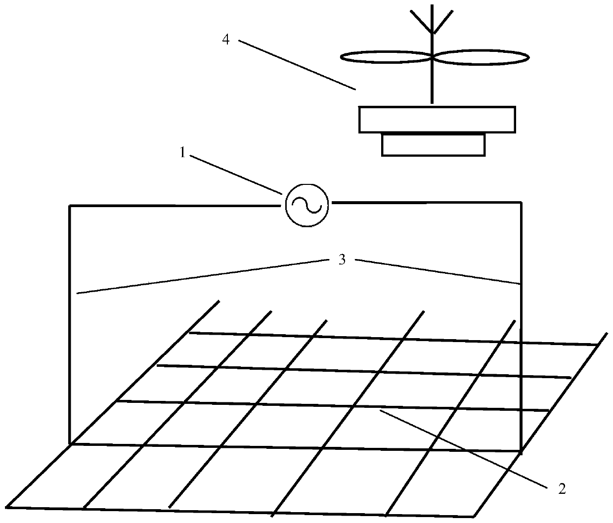
[0025] figure 1 It is a schematic diagram of the principle of a non-destructive detection system for grounding mesh conductor status of the present invention. A non-destructive detection system for the state of grounded mesh conductors of the present invention is composed of three parts: a signal transmitting system 1, a signal receiving system and a background terminal. The signal transmitting system injects a sine wave signal current of a certain frequency and a certain current intensity into the grounding grid 2 through the two upper guide wires 3 of the grounding grid 2 . Using the helicopter 4 carrying the magnetic field detection unit and the magnetic field data wireless transmission unit to cruise and measure the horizontal space above the ground surface of the ground grid 10CM, the location infor...


PUM


Abstract

Disclosed is a non-destructive testing system and method for a grounding mesh conductor state. A signal transmitting system injects a sine wave signal of a certain frequency and a certain current intensity into a grounding network; a signal detection and acquisition device carried by a remote control drone of a signal receiving system quickly cruises on a ground surface of the grounding network for data acquisition, and completes the detection of an excitation magnetic field of a grounding network branch conductor in an adjacent spatial region on the ground surface. A Beidou BDS and GPS dual-mode satellite positioning and navigation system, a magnetic field detection unit and a data wireless transmission system carried by the remote control drone wirelessly transmit spatial coordinate datainformation together with the synchronously collected magnetic field data information to a terminal upper computer system composed of a wireless receiving unit, a computer and software. By receiving,storing, summarizing and analyzing data in real time, magnetic field distribution on the ground surface of the grounding network is quickly obtained, and a grounding network state and a safety performance evaluation result of the grounding network are outputted. The present invention has the characteristics of simple operation, high work efficiency and accurate diagnosis.

Description

technical field [0001] The invention belongs to the technical field of power system detection, and in particular relates to a non-destructive detection system and method for the state of a grounding mesh conductor. Background technique [0002] The grounding grid is a necessary facility for power transmission and distribution substations, and the grounding grid plays a very important role in the safe operation of the power system. The first is the need for work, providing a common reference ground for various electrical equipment in the substation; the other is also the need for safety protection, when the power system has a short-circuit fault or is struck by lightning, it can quickly discharge the fault current and reduce the safety of the protected area. The ground potential rises to protect the personal safety of the staff and the safe and normal operation of various electrical equipment. The grounding grid of a substation is usually welded with materials such as flat s...

Claims


Application Information

Patent Timeline
IPC IPC(8): G01R31/08G01N27/83
Inventor 张树亮徐洪福宋文乐刘东亮王向阳谷雨刘杨李响朱桂东刘洋王璐
Owner STATE GRID HEBEI ELECTRIC POWER CO LTD
Features
  • R&D
  • Intellectual Property
  • Life Sciences
  • Materials
  • Tech Scout
  • Unparalleled Data Quality
  • Higher Quality Content
  • 60% Fewer Hallucinations
Learn More