FP (Fabry-Perot) spectrum structure for spectral addressing measurement, preparation method and optimal microscope

A spectrum and addressing technology, applied in the field of optical microscopes, can solve the problems of high structural and environmental stability and controllability requirements of the microscopic imaging system, complex configuration of light source and imaging optical path, lack of spectral image acquisition, etc. The light intensity of the image field and its spectrum requirements, the imaging light field has good adaptability, and the effect of simple operation

Inactive Publication Date: 2019-05-14
NANJING OPY ELECTRONICS TECH CO LTD
View PDF8 Cites 0 Cited by
  • Summary
  • Abstract
  • Description
  • Claims
  • Application Information

AI Technical Summary

Problems solved by technology

[0003] However, existing optical microscopes have some technical defects in generating spectral images: the first method has the disadvantages of complex optical path and lack of real-time acquisition of spectral images; The structure and environmental stability and controllability requirements of the micro-imaging system are high, and the above-mentioned third method requires the configuration of a precision servo mechanism with a relatively complex structure and driving control method

Method used


Image

  • FP (Fabry-Perot) spectrum structure for spectral addressing measurement, preparation method and optimal microscope
  • FP (Fabry-Perot) spectrum structure for spectral addressing measurement, preparation method and optimal microscope
  • FP (Fabry-Perot) spectrum structure for spectral addressing measurement, preparation method and optimal microscope

Examples


Embodiment Construction

[0043] In order to make the object, technical solution and advantages of the present invention clearer, the present invention will be further described in detail below in conjunction with the accompanying drawings and embodiments. It should be understood that the specific embodiments described here are only used to explain the present invention, not to limit the present invention. In addition, the technical features involved in the various embodiments of the present invention described below can be combined with each other as long as they do not constitute a conflict with each other.

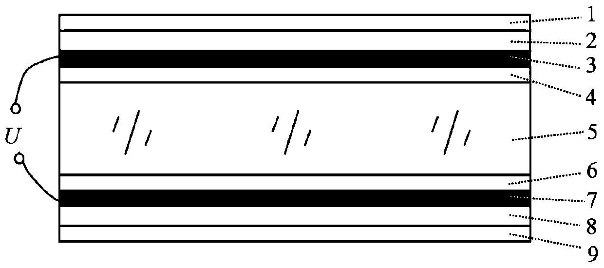
[0044] Such as image 3 As shown, the FP spectrum structure used in the spectrum addressing measurement and adjustment of the present invention includes a first anti-reflection film 1, a first substrate 2, a pattern electrode 3, a first liquid crystal alignment layer 4, a liquid crystal layer 5 , a second liquid crystal alignment layer 6 , a common electrode 7 , a second substrate 8 , and a sec...


PUM

PropertyMeasurementUnit
thicknessaaaaaaaaaa
thicknessaaaaaaaaaa
thicknessaaaaaaaaaa

Abstract

The invention discloses an FP (Fabry-Perot) spectrum structure for spectral addressing measurement for microscopic imaging measurement, comprising a first anti-reflection film, a first substrate, a pattern electrode, a first liquid crystal orientation layer, a liquid crystal layer, a second liquid crystal orientation layer, a common electrode, a second substrate, and a second anti-reflection film,which are sequentially arranged in parallel from top to bottom; the pattern electrode and the common electrode are disposed concentrically with each other, both serve as a high reflection film, and both of the pattern electrode and the common electrode are made of a metal material; the pattern electrode comprises a plurality of rectangular sub-electrodes arranged in a symmetrical manner, and eachof the rectangular sub-electrodes is electrically insulated; each of the rectangular sub-electrodes is lead out of the pattern electrode through respective electrical connection wire and is connectedto the two ends of each external control signal together with the electrical connection wire lead out of the common electrode, respectively. The FP spectrum structure in the invention has the advantages of high spectral microscopic imaging efficiency, good target and light field adaptability, small volume and mass, and easy to be coupled with other optical opto-mechanical structures.

Description

technical field [0001] The invention belongs to the technical field of optical microscopic imaging and control, and more specifically relates to a Fabry-Perot effect (Fabry-Perot effect, FP for short) spectral structure, preparation method and optical microscope. Background technique [0002] So far, optical microscope imaging technology has mainly adopted three methods in generating spectral images. The first method is to perform spectral data measurement and analysis from the imaging optical path, and then perform spectral data processing on the microscopic image to obtain micro-nano Sequential spectrum microscopic image information of the target; the second way is to construct an interference light field on the microscopic imaging surface, and perform integrated microscopic interference imaging that can be time-sequentially measured and modulated; the third way is through diffraction Spectroscopy performs high spectral resolution microscopy imaging. [0003] However, ex...

Claims


Application Information

Patent Timeline
Patent Type & Authority Applications(China)
IPC IPC(8): G01N21/25G02F1/1343G02F1/1337
Inventor 张新宇张汤安苏
Owner NANJING OPY ELECTRONICS TECH CO LTD
Why Eureka
Try Eureka