Wireless cable chute cable joint running state monitoring device

A technology of cable intermediate joint and monitoring device, which is applied in the direction of measuring device, measuring electricity, measuring electrical variable, etc., can solve the problems such as the lack of great progress in the state detection of power cables, the difficulty of detecting the DC component, and the interference of other signals. Achieve the effect of avoiding major economic losses, reducing the scope of power outages, and ensuring normal power consumption

Inactive Publication Date: 2019-05-17
NANJING INST OF TECH
View PDF7 Cites 3 Cited by
  • Summary
  • Abstract
  • Description
  • Claims
  • Application Information

AI Technical Summary

Problems solved by technology

Common methods for off-line detection mainly include impedance method, traveling wave method and regular insulation preventive test. These methods are generally carried out under the condition of power failure, and the phenomenon of power failure should be avoided by the power system as much as possible; and the preventive test is generally It is to carry out the test on all the cables. Some cables that are originally good will cause faster aging of the cable insulation due to repeated tests at a voltage higher than the rated voltage.
On-line monitoring technologies mainly include DC component method, DC superposition method, and partial discharge method. These methods have limitations, such as DC component is not easy to be detected, easily interfered by other signals, and has large errors.
With the continuous improvement of the manufacturing level and operation requirements of high-voltage power cables, the existing detection technology has great limitations and uncertainties, so that the state detection of power cables has not made great progress

Method used


Image

  • Wireless cable chute cable joint running state monitoring device
  • Wireless cable chute cable joint running state monitoring device
  • Wireless cable chute cable joint running state monitoring device

Examples


Embodiment Construction

[0026] The present invention will be further described below in conjunction with the accompanying drawings. The following examples are only used to illustrate the technical solution of the present invention more clearly, but not to limit the protection scope of the present invention.

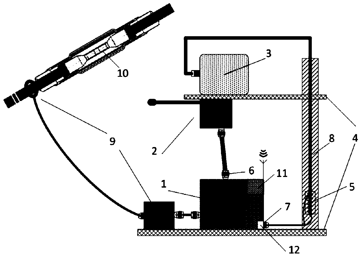
[0027] Such as figure 1 As shown, the wireless cable trench cable intermediate joint running state monitoring device provided by the present invention. The main components of the device are a sensor unit 2 , a fire extinguisher unit 3 , a single-chip microcomputer unit 1 , a wireless communication unit 11 , and an online energy storage unit 9 . The spatial layout between each unit is kept fixed by the epoxy resin support plate 4 and the epoxy resin support tube 8, the epoxy resin support plate 4 is two, and the two epoxy resin support plates 4 are arranged in parallel, respectively the first Support plate and the second support plate; the sensor unit 1 and the fire extinguisher unit 3 are loca...


PUM


Abstract

The invention discloses a wireless cable chute cable joint running state monitoring device comprising a sensor unit, a single chip microcomputer unit, a wireless communication unit, a fire extinguisher unit and an online energy acquiring unit; the sensor unit is used for collecting temperature and humidity signals, electromagnetic field distribution signals, ultraviolet flame signals and smoke signals around a cable joint, and transmitting the signals to the single chip microcomputer unit; the single chip microcomputer is applied to ADC data collection, sensor signal operation treatment, switch signal output and wireless communication unit data exchange; the fire extinguisher unit is used for receiving the switch signals of the single chip microcomputer unit for working; and the online energy acquiring unit is used for providing working power for all the abovementioned units. The wireless cable chute cable joint running state monitoring device provided by the invention has the advantages that the cable chute with fault warning is overhauled in advance through monitoring the working condition of the cable chute cable joint in real time; meanwhile, extinguishment is automatically started when there is a fire, the cable is prevented form being damaged, and the relatively serious results such as override trip are avoided.

Description

technical field [0001] The invention relates to a wireless monitoring device for the running state of a cable intermediate joint in a cable trench, and belongs to the technical fields of power electronics, high voltage and insulation, single-chip microcomputer technology, and signal processing and analysis. Background technique [0002] With the continuous and rapid growth of my country's economy, the demand for domestic electricity and business electricity is increasing. As one of the important carriers for the transmission of electric energy, the reliability of power cables is of great significance. Under the long-term complex operating environment, the power cable is affected by electric, thermal and chemical effects, and its insulation quality gradually deteriorates, which will eventually lead to insulation damage. The cable joint is the weakest link in the insulation of the cable line, and it is prone to defects that lead to operational failures. [0003] The monitori...

Claims


Application Information

Patent Timeline
Patent Type & Authority Applications(China)
IPC IPC(8): G01R31/04G01R29/08G01J1/00G01N15/06G01R31/12G01D21/02
Inventor 倪喜军张东东李先允王书征
Owner NANJING INST OF TECH
Why Eureka
Try Eureka