
A welding method for the shell and the flange of a thick plate container with a thickness of more than 30 mm

A container shell and welding method technology, applied in welding equipment, arc welding equipment, manufacturing tools, etc., can solve the problems of large flange welding deformation, reduce the welding workload of flange and shell, and achieve welding efficiency Improve and reduce the difficulty of group pairing and eliminate the effect of deformation

Active Publication Date: 2021-04-02
LUXI IND EQUIP
View PDF12 Cites 0 Cited by
  • Summary
  • Abstract
  • Description
  • Claims
  • Application Information

AI Technical Summary

Problems solved by technology

[0003] In view of the deficiencies in the above-mentioned prior art, the present invention provides a welding method for the shell and flange of a thick plate container with a thickness of more than 30mm, which reduces the welding workload between the flange and the shell, and solves the problem of large amount of flange welding deformation , effectively ensure the levelness and verticality of flange welding, improve the quality of equipment production and effectively reduce the production risk

Method used


Image

  • A welding method for the shell and the flange of a thick plate container with a thickness of more than 30 mm
  • A welding method for the shell and the flange of a thick plate container with a thickness of more than 30 mm
  • A welding method for the shell and the flange of a thick plate container with a thickness of more than 30 mm

Examples


Embodiment 1

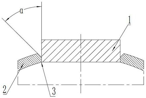
[0025] A welding method for the shell and flange of a thick plate over 30mm. The thickness of the shell is 30mm, and the material is Q345R. First, the flange hole is processed on the shell by a machine tool. The inner diameter of the flange hole is larger than the outer diameter of the flange. Use grinding equipment to grind the inner surface of the flange hole, the roughness of the inner surface of the flange hole is Ra6.3, and then use air gouging to process a single-sided groove on the outer edge of the flange hole shell ("K" type groove a ), the angle α between the first unilateral bevel and the vertical direction is 30°, and the length of the blunt side 3 is 10mm; by adjusting the relative position of the shell and the flange, the flange is welded on the blunt side 3 to ensure the horizontal The angle is 0.2mm, and the perpendicularity is 0.2mm; the "K" type groove a is welded by the welding rod manual welding process, and the bottom layer of the weld seam is made of Ele...

Embodiment 2

[0032] A welding method for the shell and flange of a thick plate over 30mm. The thickness of the shell is 40mm, and the material of the shell is S30408. First, the flange hole is processed on the shell by a machine tool. The outer diameter is smaller than 5mm, use grinding equipment to grind the inner surface of the flange hole, the roughness of the inner surface of the flange hole is Ra1.6, and then use air gouging to process the single-side bevel ("K" type bevel) on the outer edge of the flange hole shell port a), the angle α between the first unilateral bevel and the vertical direction is 50°, and the length of the blunt side 3 is 50mm; by adjusting the relative position of the shell and the flange, the flange is welded on the blunt side 3, Ensure that the levelness is 0.4mm and the verticality is 0.4mm; the "K" type groove a is welded by the welding rod manual welding process, and the bottom layer of the weld seam is made of Electrode manual welding, filling layer adopts...

Embodiment 3

[0039] A welding method for the shell and flange of a thick plate over 30mm. The thickness of the shell is 60mm, and the material of the shell is Q345R. The diameter is smaller than 3mm, use the grinding equipment to grind the inner surface of the flange hole, the inner surface roughness of the flange hole is Ra3.5, and then use air gouging to process the single-sided groove ("K" type groove) on the outer edge of the flange hole shell a), the angle α between the first unilateral bevel and the vertical direction is 45°, and the length of the blunt side 3 is 30 mm; by adjusting the relative position of the shell and the flange, the flange is welded on the blunt side 3 to ensure The horizontality is 0.8mm, and the verticality is 0.8mm; the "K" type groove a is welded by the welding rod manual welding process, and the bottom layer of the weld seam is made of Electrode manual welding, filling layer adopts Electrode manual welding, cover layer adopts Manual welding with electrod...


PUM

PropertyMeasurementUnit
thicknessaaaaaaaaaa
thicknessaaaaaaaaaa
thicknessaaaaaaaaaa

Abstract

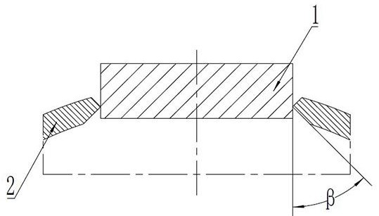
The invention discloses a method of welding a thick plate container shell with the thickness of being 30mm or above and a flange. The method mainly comprises the six steps of machining of a flange hole, machining of outer single-edge grooves (K-shaped grooves a) of the flange hole, assembly of the shell and the flange, welding of the outer grooves of the flange hole, machining of inner single-edgegrooves (K-shaped grooves b) of the flange hole and welding of the inner grooves of the flange hole. By the adoption of the method, conventional V-shaped grooves of the flange are improved to form the K-shaped grooves, the welding material filling quantity is reduced by about 10%, and the welding efficiency is improved by 20% or above. The shell and the flange are assembled and welded through a reserved truncated edge, rigid fixation of the flange is enhanced by the truncated edge, the assembly difficulty of the flange is effectively reduced, and the assembly efficiency is improved by 50% orabove. The flange and the shell are symmetrically welded in a subsection mode, the welding stress is effectively reduced, the deformation in the flange welding process is eliminated, and the perpendicular degree and the horizontal degree meet the technological requirements of equipment utilization. The welding efficiency is improved as the welding quality is guaranteed, and the requirement of welding of the thick plate container shell with the thickness of being 30mm or above and the flange is met.

Description

technical field [0001] The invention relates to the field of flange welding of container shells, in particular to a welding method for a container shell and a flange of a thick plate of more than 30 mm. Background technique [0002] In chemical production, the reactor is a common container with a stirring device, which is often used to complete processes such as sulfonation, nitration, alkylation, polymerization, and condensation. The agitator is generally connected to the container through a flange, and the rotation of the external motor Drive the stirring shaft to rotate, so that the materials in the container are fully mixed and reacted. Therefore, the installation of the stirring device is the most important link in the production of the reactor. Once the stirring device is installed deflected, on the one hand, the stirring shaft will be affected by the deflection force, which will affect the service life of the stirring device. On the other hand, the deflection of stirr...

Claims


Application Information

Patent Timeline
Patent Type & Authority Patents(China)
IPC IPC(8): B23P15/00B23K9/02
Inventor 邹伟梁兆鹏王凯威高建君鲍士民耿磊姚传滨王景才孟杰刘世国于子健高文升刘云邢瑞鹏
Owner LUXI IND EQUIP
Learn More