
Hydraulic oscillator used under oil field well

A technology for hydraulic oscillators and oilfield wells, used in vibration drilling, wellbore/well components, vibration generating devices, etc., can solve the problems of limited vibration impact momentum, large hydraulic pressure drop, and high cost, and achieve vibration frequency and impact. The effect of large momentum range, high kinetic energy conversion efficiency and small pressure loss

Active Publication Date: 2019-05-21
SHANDONG LUHAI GASOLINEEUM EQUIP
View PDF9 Cites 6 Cited by
  • Summary
  • Abstract
  • Description
  • Claims
  • Application Information

AI Technical Summary

Problems solved by technology

[0004] The turbine drive eccentric method is simple and easy to implement, but the hydraulic pressure drop is too large, there are mechanical friction and eddy current losses, the gap between the rotating parts is easy to jam, the vibration impact momentum is limited, and the synchronization cannot be guaranteed when multi-stage combination; the screw motor method has high efficiency , Radial impact momentum is large, etc., but the processing is difficult, so the cost is very high

Method used


Image

  • Hydraulic oscillator used under oil field well
  • Hydraulic oscillator used under oil field well
  • Hydraulic oscillator used under oil field well

Examples


Embodiment Construction

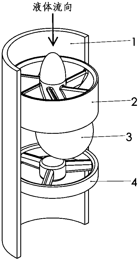
[0017] In order to have a clearer understanding of the technical features, purposes and effects of the present invention, several examples are described below. The main component parameters in the embodiment: the pipeline 1 is a 5-1 / 2 inch oil casing with an inner diameter of 125.7 mm; the solid ball 3 is a chrome-plated steel ball with a diameter of 80 mm.

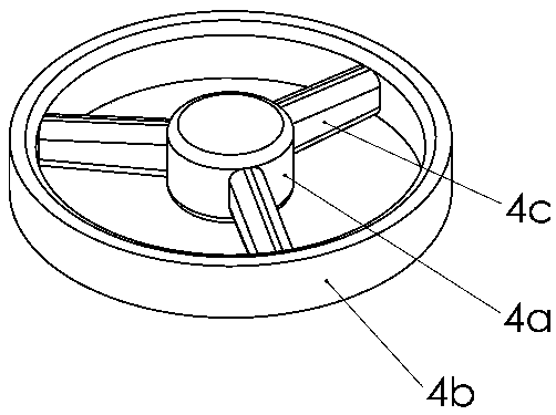
[0018] as attached figure 1 As shown, the liquid flows into the circular pipe 1 from the direction indicated by the arrow in the figure, and after passing through the vane plate 2 fixedly connected with the pipe, a swirling flow is formed, and the swirling flow drives the solid ball 3 to move in the circumferential direction. Due to the centrifugal force, the solid ball 3 The ball 3 rolls and revolves closely against the inner wall of the pipe 1 in the space between the guide vane disc 2 and the ball stopper 4, and exhibits radial vibration to the outside.

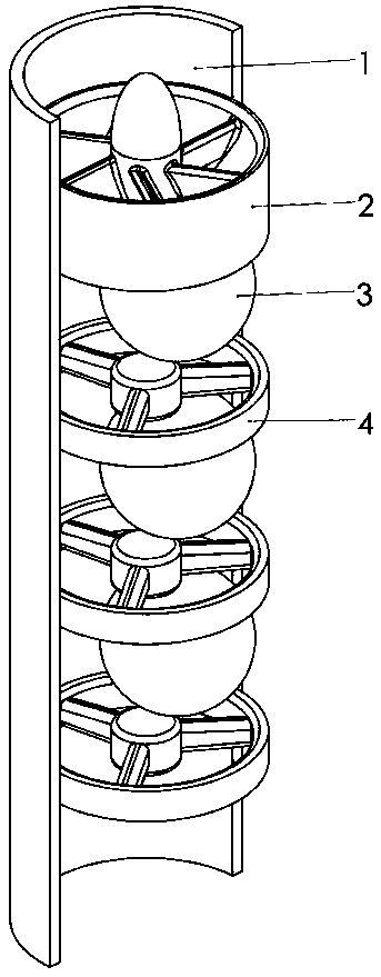
[0019] image 3 It is a structural schematic diagram of a mult...


PUM


Abstract

The invention provides a hydraulic oscillator used under an oil field well. The hydraulic oscillator comprises a circular pipeline 1 through which liquid flows, and a guide vane disc 2 fixedly connected with the pipeline; and the hydraulic oscillator is characterized in that the same pipeline 1 also comprises a solid ball 3 which is positioned at the downstream of the guide vane disc 2 and has thediameter smaller than the inner diameter of the pipeline 1, and a ball baffle 4 positioned at the downstream of the solid ball 3; fluid flows through the guide vane disc 2 to form rotational flow; the solid ball 3 is driven by the rotational flow to move in the circumferential direction, and the solid ball 3 can roll close to the inner wall of the pipeline 1 under the action of centrifugal forceand is limited by the ball baffle 4; and finally the solid ball 3 only can continuously roll in the circumferential direction along the pipe wall and revolve with the axis of the pipeline 1 as the center in the space between the guide vane disc 2 and the ball baffle 4 to generate radial vibration.

Description

technical field [0001] The invention relates to the field of oil and gas well engineering, in particular to a downhole tool used for drilling and cementing operations in oil fields, in particular to hydraulically driven oscillators that generate radial (also known as transverse) vibrations. technical background [0002] In drilling operations, in many cases, it is necessary to reduce the drilling resistance with the help of drilling tool vibration; in the cementing process, vibration is often used to break through the resistance of running casing and assist in cleaning the well wall. At the same time, vibration can effectively improve the cementing quality of cement slurry. Due to the limitation of the pipe diameter space, in the existing hydraulic power downhole vibration tools, compared with the axial vibration, it is more difficult for the radial vibration to achieve the ideal frequency and impact momentum. [0003] At present, the methods of using hydraulic power to gene...

Claims


Application Information

Patent Timeline
IPC IPC(8): E21B7/24E21B28/00
Inventor 杜思慷
Owner SHANDONG LUHAI GASOLINEEUM EQUIP
Learn More