Suspended crucible cover with height capable of being adjusted in real time for growth of sapphire single crystal by KY method and KY-method sapphire single crystal growth device
A growth device, sapphire technology, applied in the direction of single crystal growth, single crystal growth, crystal growth, etc., can solve the problems of large proportion, instability, inappropriate shoulder gradient, etc., to achieve large space, ensure stability, and ensure thermal insulation sexual effect
- Summary
- Abstract
- Description
- Claims
- Application Information
AI Technical Summary
Problems solved by technology
Method used
Image
Examples
Embodiment 1
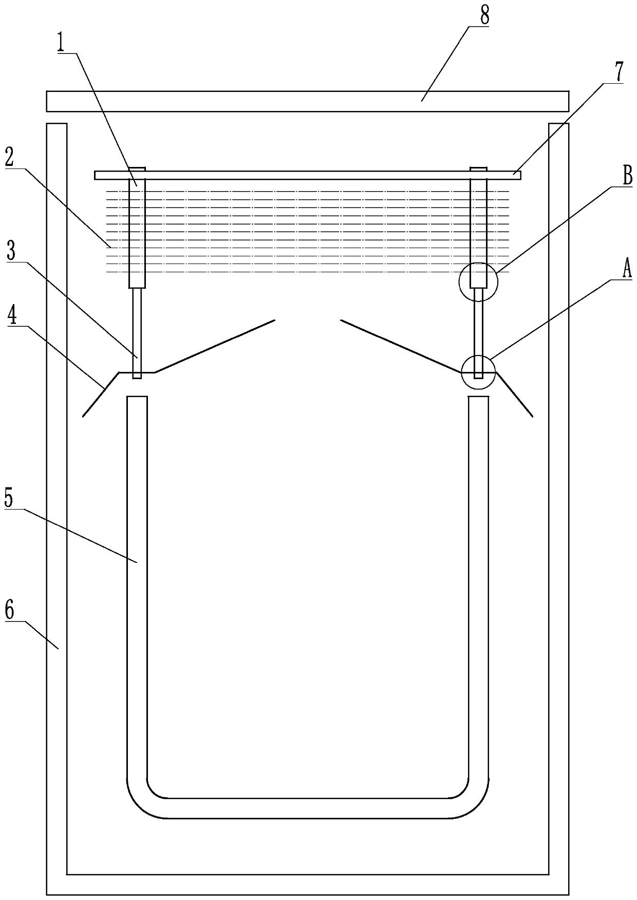
[0050] Embodiment 1: refer to Figure 1~3 , is a schematic structural diagram of Embodiment 1 of the present invention, a
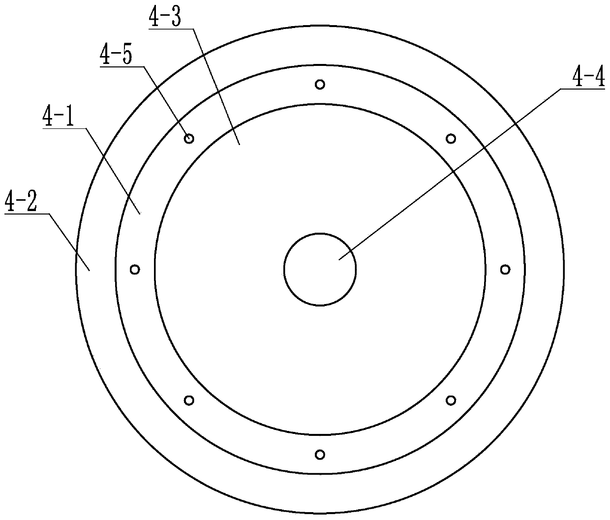
[0051] The crucible cover used on the KY method sapphire single crystal growth crucible, i.e. the specific type crucible cover, includes a cover body 4-1, a cover eaves 4-2 and a cap 4-3, the cover body 4-1 is ring-shaped, and the cover body 4-1 is provided with a through hole on the surface, and the through hole is a hoisting hole 4-5. The cover eaves 4-2 are in the shape of a cylindrical tube or a horn-shaped tube, and one open end of the cover eaves 4-2 is connected to the cover The outer circle of the body 4-1 is connected, the other end is a free end, the cap 4-3 is trumpet-shaped, the larger opening end of the cap 4-3 is connected with the inner circle of the cover body 4-1, and the other end is a free end , the cover eaves 4-2 and the cap 4-3 are respectively arranged on both sides of the plane where the cover body 4-1 is located.
[0052] The co...
Embodiment 2
[0058] Embodiment 2: refer to Figure 4 , is a schematic structural diagram of Embodiment 2 of the present invention. Compared with Embodiment 1, the difference of this embodiment is that the suspension rod B3 and the cover body 4-1 are connected by bolts, and the bolts are made of tungsten or molybdenum. become.
[0059] Suspension bar B3 passes cover body 4-1, fixes bolt respectively at cover body 4-1 both sides, and the bolt on both sides is pressed on cover body 4-1, has reached fixing.
Embodiment 3
[0060] Embodiment 3: refer to Figure 5 , is a schematic structural diagram of Embodiment 3 of the present invention. Compared with Embodiment 1, the difference of this embodiment is that: the connecting end of the suspension rod B3 and the cover body 4-1 is provided with a stopper 3-1. In the actual working state, the suspension The rod B3 is vertical, and under the action of gravity, the cover body falls on the stopper 3-1, and the stopper 3-1 supports the cover body 4-1, that is, the cover body 4-1 hangs on the stopper 3-1 Above, the stopper is made of tungsten or molybdenum.
PUM
 Abstract
Description
Claims
Application Information
 - R&D
- Intellectual Property
- Life Sciences
- Materials
- Tech Scout
- Unparalleled Data Quality
- Higher Quality Content
- 60% Fewer Hallucinations
Browse by: Latest US Patents, China's latest patents, Technical Efficacy Thesaurus, Application Domain, Technology Topic, Popular Technical Reports.
© 2025 PatSnap. All rights reserved.Legal|Privacy policy|Modern Slavery Act Transparency Statement|Sitemap|About US| Contact US: help@patsnap.com


