
Assembling joint of reinforced concrete column and assembling method

A technology for reinforced concrete columns and assembling nodes, which can be applied to buildings, building structures, etc., can solve problems such as difficult to meet, gap in seismic performance of cast-in-place nodes, lag, etc., to simplify construction, promote industrial development, and enhance applicability. Effect

Pending Publication Date: 2019-05-28
CHONGQING UNIV
View PDF9 Cites 6 Cited by
  • Summary
  • Abstract
  • Description
  • Claims
  • Application Information

AI Technical Summary

Problems solved by technology

The existing assembly joints mainly focus on the wet column-column joint form, while the theoretical research on the dry column-column joint form is still lagging behind and needs to be further explored. Although the existing dry joint joints are greatly shortened The construction period is shortened, but there is still a certain gap in the seismic performance of cast-in-place joints, and it is difficult to meet the requirements of "strong joints, weak components"

Method used


Image

  • Assembling joint of reinforced concrete column and assembling method
  • Assembling joint of reinforced concrete column and assembling method
  • Assembling joint of reinforced concrete column and assembling method

Examples


Embodiment Construction

[0028] The present invention will be described in detail below in conjunction with accompanying drawing and specific embodiment:

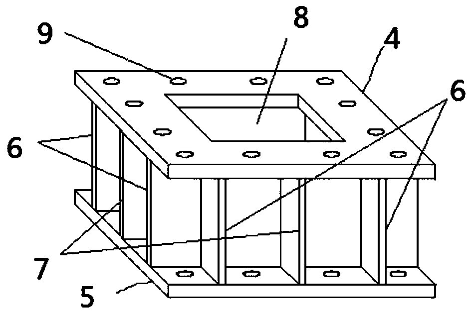
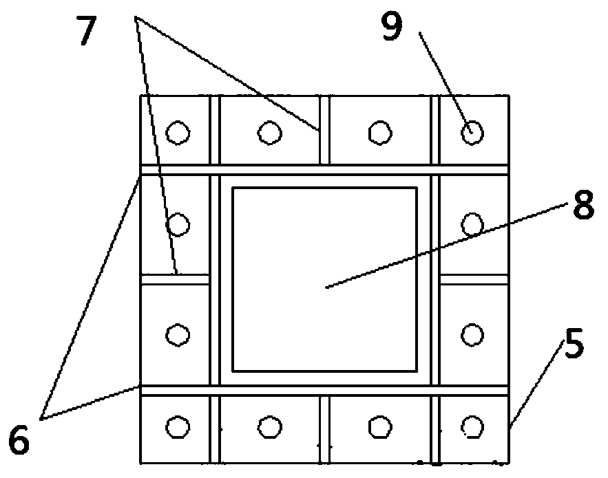
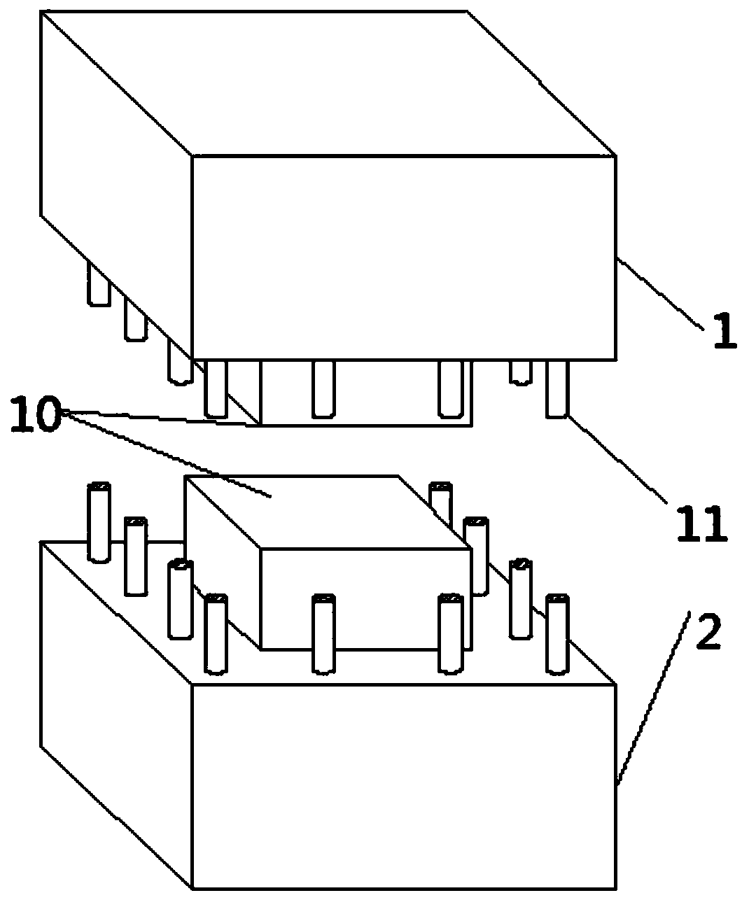
[0029] Such as Figure 1-Figure 4 As shown, the assembly node of the present invention includes a prefabricated upper column 1, a prefabricated lower column 2 and a prefabricated steel node unit 3 between the prefabricated upper column 1 and the prefabricated lower column 2;

[0030] Wherein, the prefabricated steel node unit 3 includes an upper end plate 4, a lower end plate 5 and a connecting plate between the upper end plate 4 and the lower end plate 5, the connecting plate includes four webs 6 and each The stiffening ribs 7 on the side wall of the web, and the four webs 6 are interspersed and welded together, so that the web 6 is in the shape of a "well", and the central part of the web 6 in the shape of a "well" The hole is a mortise 8, one end of each stiffening rib 7 is welded to the middle of the side wall of the corresponding web 6, and t...


PUM


Abstract

The invention discloses an assembling joint of a reinforced concrete column and an assembling method. The assembling method comprises the following steps: spreading a thin layer of bed mortar on a topsurface of a prefabricated lower column, inserting a column end tenon of the prefabricated lower column into a mortise of a prefabricated steel node unit, matching a positioning hole in a lower end plate of the prefabricated steel node unit with a positioning longitudinal bar of the prefabricated lower column, and connecting the same by using a bolt, so as to enable the prefabricated lower columnto be connected with the prefabricate steel node unit; filling appropriate amount of high-performance mortar into the mortise of the prefabricated steel node unit; inserting the column end tenon of aprefabricated upper column into the mortise of the prefabricated steel node unit so that the mortar can just overflow from a contact surface after the column end tenon of the prefabricated upper column is inserted into the mortise, and finally matching the positioning hole in the upper end plate of the prefabricated steel node unit with the positioning longitudinal bar of the prefabricated uppercolumn, and connecting the same by using the bolt, so as to form an entire assembling node. The layout location of the assembling node is comparatively flexible, the overhauling is convenient, and theassembling node has strong applicability.

Description

technical field [0001] The invention relates to the field of construction, in particular to an assembly node and an assembly method of a reinforced concrete column. Background technique [0002] Since the early days of the founding of the People's Republic of China, my country's assembly joint system has been applied in multi-storey buildings one after another. The assembly joint has the advantages of short construction period, high construction efficiency, less wet work, and environmental protection. It is a trend in the development of my country's construction industry. The assembly joint is a whole formed by the beam and column components being transported to the construction site after being prefabricated in the prefabrication factory or on site, and then hoisted and connected. Column is an important component that bears horizontal and vertical loads in a frame structure. In order to obtain better mechanical properties, the connection between columns will be particularly...

Claims


Application Information

Patent Timeline
Patent Type & Authority Applications(China)
IPC IPC(8): E04B1/21
Inventor 刘立平余杰李维斯
Owner CHONGQING UNIV
Learn More