Carbon dioxide welding machine and welding method thereof
A technology of carbon dioxide and fusion splicing machine, which is applied in the coupling of optical waveguide and other directions, can solve the problems of short service life of the fusion splicing device between optical fiber and end cap, difficulty in accurately controlling the size of the fusion splicing point, and inconsistent heating of optical materials, etc., and achieves a higher success rate and longer The effect of service life and ease of welding
- Summary
- Abstract
- Description
- Claims
- Application Information
AI Technical Summary
Problems solved by technology
Method used
Image
Examples
specific Embodiment approach 1
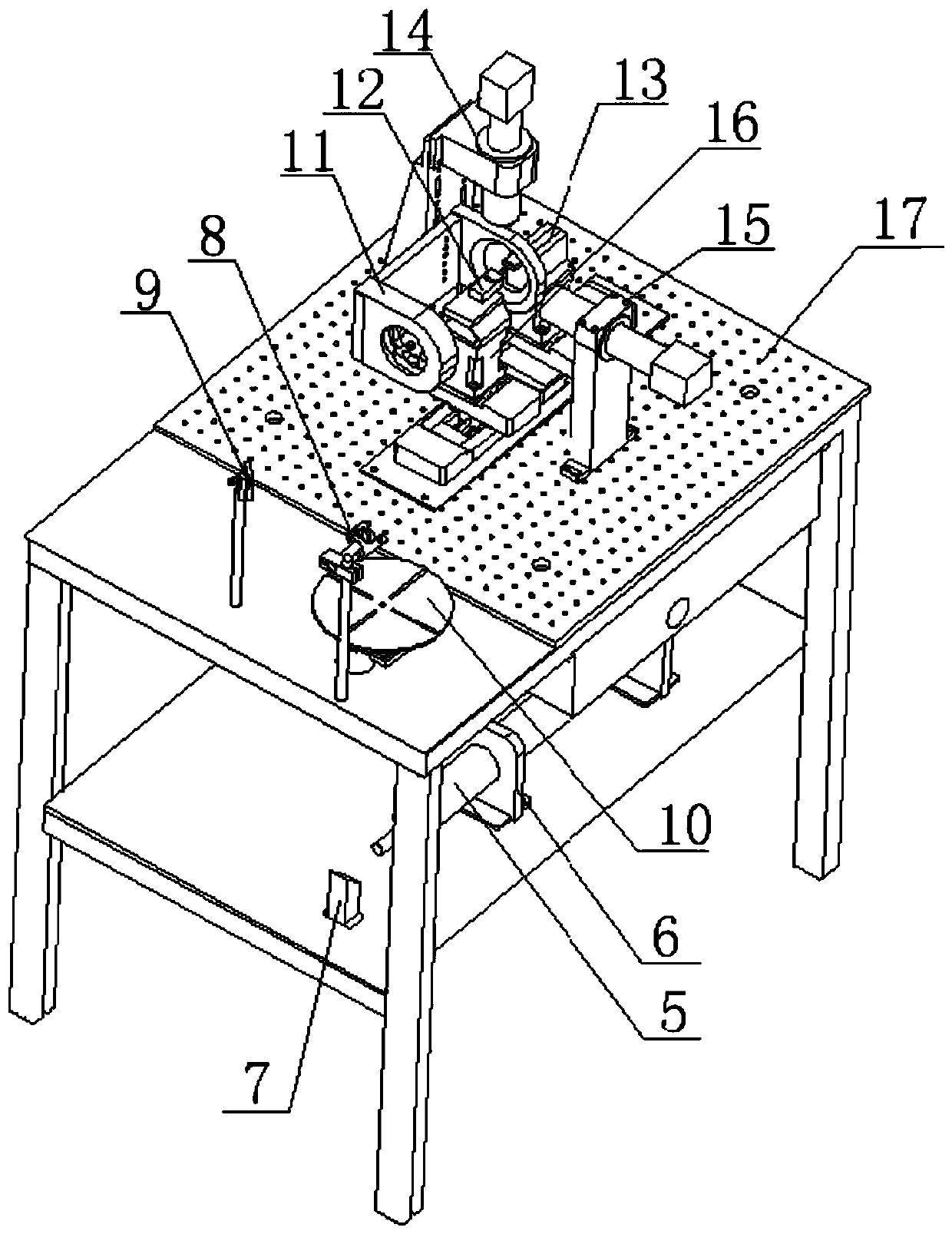
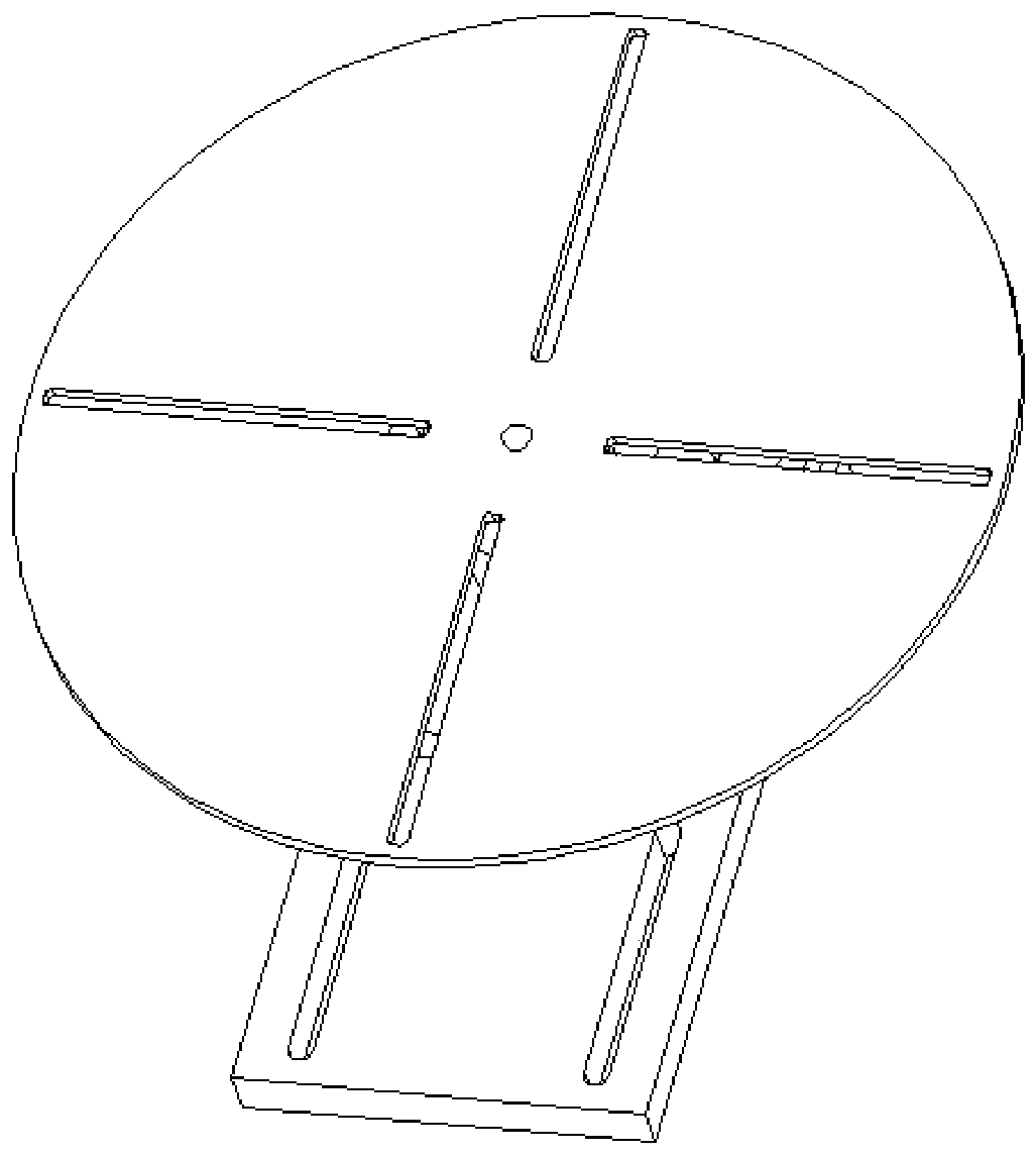
[0044] Specific implementation mode one: combine Figures 1 to 7 Describe this embodiment in detail. A carbon dioxide welding machine in this embodiment includes a carbon dioxide laser 5, a first 45° reflector 7, a second 45° reflector 8, a third 45° reflector 9, an optical chopper 10, a laser Focusing device 11, first clamping device 12, second clamping device 13, three-dimensional electric translation table 16 and operating table 17;
[0045] Described operating platform 17 comprises upper floor work surface and bottom work surface;
[0046] The carbon dioxide laser 5 and the first 45° reflector 7 are arranged on the bottom working table;
[0047] The second 45° mirror 8, the third 45° mirror 9, the optical chopper 10, the laser focusing device 11, the first fixture device 12, the second fixture device 13 and the three-dimensional electric translation platform 16 are arranged on the upper floor on the working table; and a through hole is set on the upper working table corr...
specific Embodiment approach 2
[0070] Embodiment 2: This embodiment differs from Embodiment 1 in that: the front end of the total reflection light cone 1 is made of an aluminum reflector or a reflector coated with a reflective film. Others are the same as the first embodiment.
[0071] According to different laser beam types in this specific embodiment, the total reflection light cone 1 can be classified into aluminum reflectors or reflective film-coated reflectors.
specific Embodiment approach 3
[0072] Specific implementation mode three: combination Figure 8 and 9 This embodiment is specifically described. The difference between this embodiment and the first or second embodiment is that a vertical camera imaging calibration device 14 is arranged above the second total reflection mask 2-2, and a horizontal camera imaging calibration device is arranged in the horizontal direction. device 15. Others are the same as those in Embodiment 1 or 2.
[0073] In this specific embodiment, the vertical camera imaging calibration device 14 and the horizontal camera imaging calibration device 15 conduct observations in both vertical and horizontal directions, and the purpose of the observations is to allow the parts to be welded to reach a predetermined position.
[0074] The focused small halo of this specific embodiment is fixed because its irradiation area is fixed, so by moving the first part to be welded to match the position of the small halo, and then the distance of the a...
PUM
 Abstract
Description
Claims
Application Information
 - R&D
- Intellectual Property
- Life Sciences
- Materials
- Tech Scout
- Unparalleled Data Quality
- Higher Quality Content
- 60% Fewer Hallucinations
Browse by: Latest US Patents, China's latest patents, Technical Efficacy Thesaurus, Application Domain, Technology Topic, Popular Technical Reports.
© 2025 PatSnap. All rights reserved.Legal|Privacy policy|Modern Slavery Act Transparency Statement|Sitemap|About US| Contact US: help@patsnap.com


