Rigid gas-liquid coalescing filter element, and preparation method and device thereof

A coalescence, gas-liquid technology, applied in separation methods, chemical instruments and methods, filtration separation, etc., can solve problems such as skeleton damage, filter failure, and unsatisfactory filtration effects, and achieve the effect of improving rigidity and reducing costs

Pending Publication Date: 2019-06-07
CHINA UNIV OF PETROLEUM (BEIJING)
View PDF24 Cites 4 Cited by
  • Summary
  • Abstract
  • Description
  • Claims
  • Application Information

AI Technical Summary

Problems solved by technology

Flexible materials have no compressive strength, and will undergo compression deformation under high pressure, and the internal structure of the filter material will be severely deformed, resulting in changes in the pore structure, affecting the coalescence and drainage process, resulting in unsatisfactory filtration effects
Moreover, under high-pressure conditions, the density of the gas increases significantly, and the buoyancy of the droplets increases accordingly, resulting in a relative slowdown in the discharge rate of the liquid in the drainage layer, and the formation of liquid accumulation in the drainage layer. The amount of liquid accumulation increases and the gas circulation When the area is reduced, the gas velocity flowing through the drainage layer will increase, resulting in the enhanced scouring effect of the gas on the liquid in the drainage layer. When the liquid volume reaches a certain level, that is, the saturated fluid volume, it will cause serious secondary entrainment
In addition, the material of the inner frame is usually made of metal. If the gas and liquid droplets contain corrosive components, it is easy to cause damage to the frame and cause the filter to fail.

Method used


Image

  • Rigid gas-liquid coalescing filter element, and preparation method and device thereof
  • Rigid gas-liquid coalescing filter element, and preparation method and device thereof
  • Rigid gas-liquid coalescing filter element, and preparation method and device thereof

Examples


Embodiment Construction

[0046] The following will clearly and completely describe the technical solutions in the embodiments of the present invention with reference to the accompanying drawings in the embodiments of the present invention. Obviously, the described embodiments are only some, not all, embodiments of the present invention. Based on the embodiments of the present invention, all other embodiments obtained by persons of ordinary skill in the art without making creative efforts belong to the protection scope of the present invention.

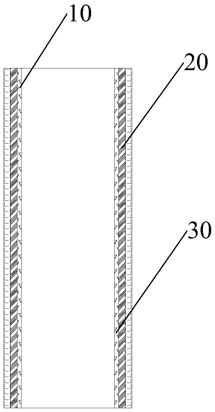
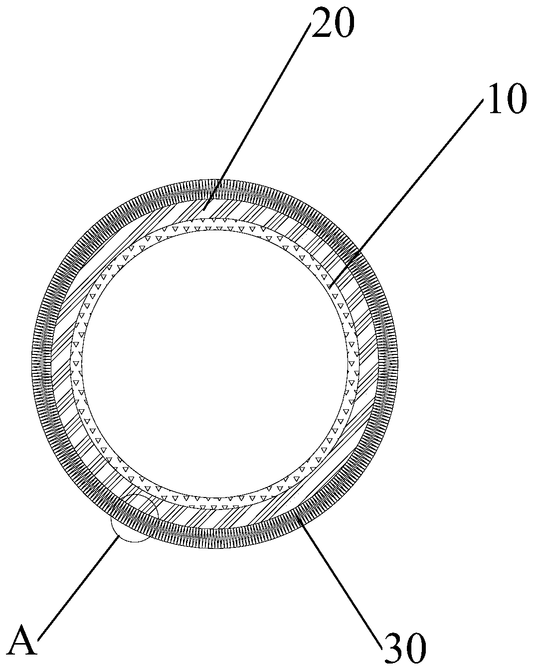
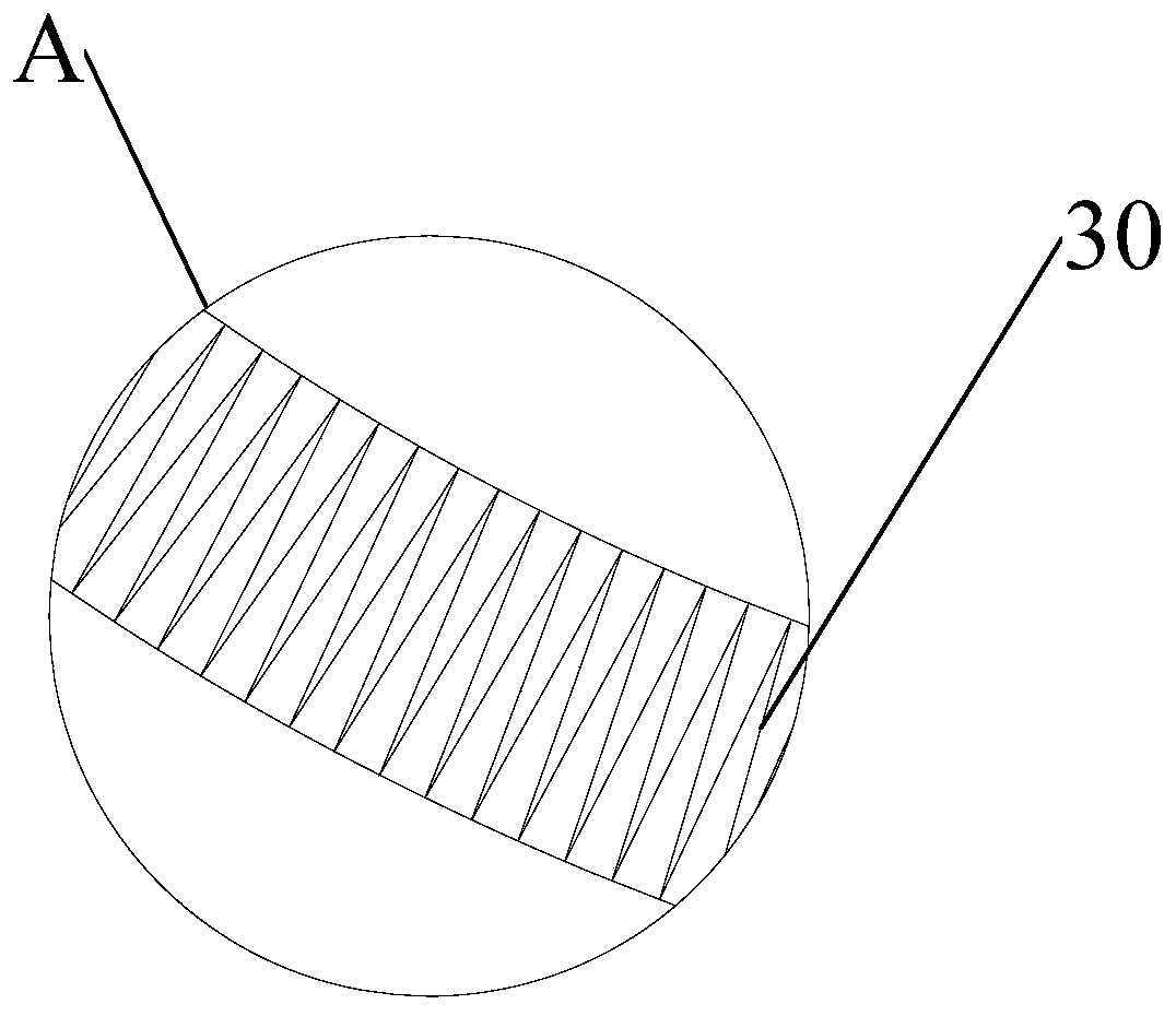
[0047] According to one aspect of the present invention, this embodiment discloses a rigid gas-liquid coalescing filter element. Such as Figure 1-Figure 3 As shown, in this embodiment, the rigid gas-liquid coalescing filter element includes a coalescing layer 20 and a liquid drainage layer 30 . The coalescing layer 20 surrounds the outside of the central air inlet channel for coalescing and separating droplets in the gas flowing in through the air inlet chan...


PUM

PropertyMeasurementUnit
thicknessaaaaaaaaaa
pore sizeaaaaaaaaaa
thicknessaaaaaaaaaa

Abstract

The invention provides a rigid gas-liquid coalescing filter element, and a preparation method and device thereof. The filter element comprises a coalescing layer which surrounds the outer side of a central air inlet channel and is used for coalescing and separating liquid drops flowing in from the air inlet channel, and the filter element also comprises a liquid discharging layer which surrounds the outer side of the coalescing layer and is used for providing a liquid discharging channel for condensed liquid drops, wherein the coalescing layer is formed by drying and solidifying a first flexible material containing an adhesive, the liquid discharging layer is formed by drying and solidifying a second flexible material containing an adhesive, the first flexible material containing the adhesive is obtained by carrying out vacuum suction to enable an adhesive solution to pass through the first flexible material, and the second flexible material containing the adhesive is obtained by carrying out vacuum suction to enable an adhesive solution to pass through the second flexible material. According to the invention, the strength of the gas-liquid coalescing filter element can be improved, and requirements of a high-pressure working condition can be met.

Description

technical field [0001] The invention relates to the technical field of gas-liquid filtration, in particular to a rigid gas-liquid coalescing filter element, a preparation method and a device thereof. Background technique [0002] Natural gas, coal bed methane and other process gases and dry gas seal gases usually contain liquid impurities, which will affect the safe operation of downstream related instruments and equipment. Therefore, it is necessary to filter the liquid droplets in the gas. Filtration is usually performed under high pressure conditions (such as Natural gas needs to be transported after being pressurized by a compressor station, which is carried out under the pressure of 12MPa in the third line of the West-to-East Gas Pipeline. For droplets with a particle size of 0.1 to 1 μm, coalescing filters are generally used for filtration. Coalescing filters are usually used downstream of leaf separators, mist catchers, and filter separators. Large droplets in the gas...

Claims


Application Information

Patent Timeline
Patent Type & Authority Applications(China)
IPC IPC(8): B01D46/24B01D46/00B01D39/14
Inventor 刘震苗林丰姬忠礼吴小林
Owner CHINA UNIV OF PETROLEUM (BEIJING)
Why Eureka
Try Eureka