Laser mosquito repelling equipment
A laser and equipment technology, applied in the field of laser mosquito repellent equipment, can solve problems such as inability to achieve mosquito repellent effect, high laser power requirements, disturbing mosquito sense of smell, etc., achieve wide mosquito repellent range, wide laser scanning range, and no safety hazards Effect
- Summary
- Abstract
- Description
- Claims
- Application Information
AI Technical Summary
Problems solved by technology
Method used
Image
Examples
Embodiment 1
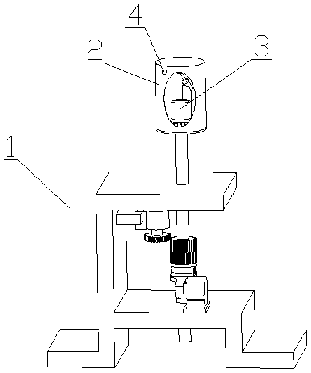
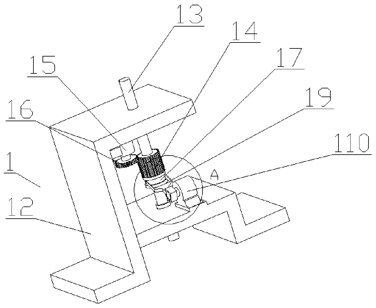
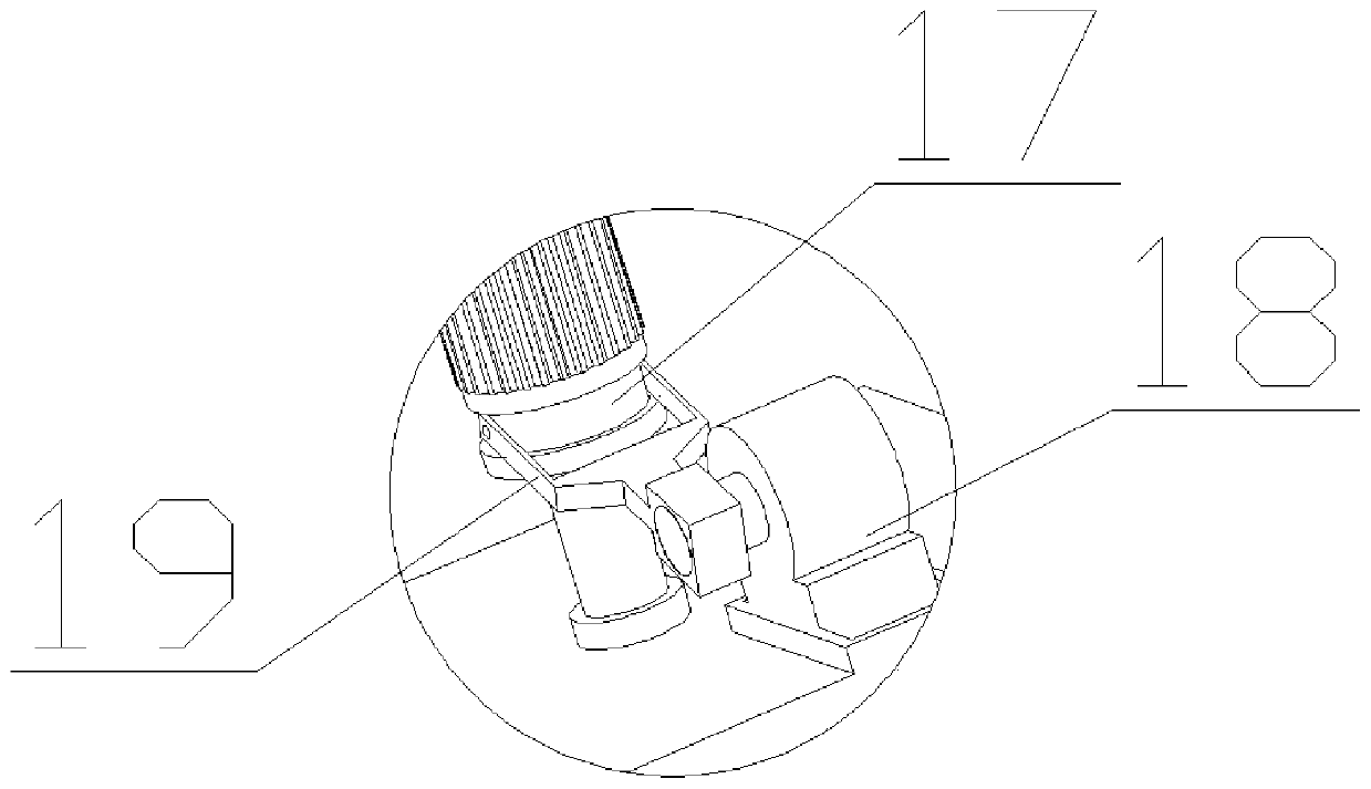
[0036] Such as Figure 1 to Figure 5 As shown, the present invention is a kind of laser mosquito repelling equipment, comprises rotating mechanism 1, is provided with protective cover 2 on rotating mechanism 1, wherein the effect of protective cover 2 has two, and one is to have the effect of dustproof, and another is to make The laser emitting mechanism 3 forms a scanning area, and the shield 2 is provided with a laser emitting mechanism 3. The laser emitting mechanism 3 includes a laser power supply 31 and a laser emitting unit 32. The laser emitting unit 32 has at least one laser emitting optical system, and the laser emitting optical system includes Semiconductor laser 321, laser collimating lens 322 and laser rotating mirror 323, laser collimating lens 322 collimates the laser light emitted by semiconductor laser 321, and the collimated laser beam is formed on the outside of shield 2 through laser rotating mirror 323 A pulsed laser scans the area.
[0037]The semiconduct...
Embodiment 2
[0050] see figure 1 - Figure 6 : On the basis of Embodiment 1, a support mechanism is added, specifically as follows:
[0051] The laser mosquito repellent device also includes a supporting mechanism 5, on which a rotating mechanism 1 is arranged, and the supporting mechanism 5 includes a load-bearing plate 51, and an adjustment assembly 52 is arranged at the bottom of the load-bearing plate 51, and the adjustment assembly 52 includes an upper leg 521 and a lower leg 522, the upper leg 521 is connected with the lower leg 522 by bolts.
[0052] The upper leg 521 is L-shaped, including a bending part A and a bending part B. The bending part A is fixedly connected to the bottom of the load-bearing plate 51. There are three rows of mounting holes on the end surface of the bending part B. The lower leg 522 is L-shaped. , including a bending part C and a bending part D, a row of through holes is arranged on the bending part C, the through holes and the installation holes are conc...
PUM
 Abstract
Description
Claims
Application Information
 - R&D
- Intellectual Property
- Life Sciences
- Materials
- Tech Scout
- Unparalleled Data Quality
- Higher Quality Content
- 60% Fewer Hallucinations
Browse by: Latest US Patents, China's latest patents, Technical Efficacy Thesaurus, Application Domain, Technology Topic, Popular Technical Reports.
© 2025 PatSnap. All rights reserved.Legal|Privacy policy|Modern Slavery Act Transparency Statement|Sitemap|About US| Contact US: help@patsnap.com


