Double lamp filament neutralizer for ion beam equipment

An ion beam and filament technology, applied in the field of ion beam, can solve the problems of shortened life, long operation time, and inability to switch quickly, and achieve the effects of convenient installation and maintenance, high neutralization efficiency, and long filament life.

Pending Publication Date: 2019-06-14
BEIJING CHUANGDENENG TECH
View PDF4 Cites 2 Cited by
  • Summary
  • Abstract
  • Description
  • Claims
  • Application Information

AI Technical Summary

Problems solved by technology

[0003] However, for this type of ion beam sputtering coating or etching equipment, the ion source neutralizer is still installed directly in front of the ion source with a single filament. The advantage of this design is that the neutralizer is completely immersed in the ion beam, and the neutralization efficiency is high. , but the filament of the neutralizer is strongly bombarded by the ion beam, the filament quickly becomes thinner and eventually burns, and the life is greatly shortened; there is no second filament backup, and it cannot be quickly switched to the second filament when the first filament is blown Filament, easy to interrupt coating or etching work
At the same time, filament material atoms are easy to pollute the vacuum chamber, affecting the coating or etching effect
In addition, the filament of the neutralizer is installed in front of the ion source, and the ion source needs to be taken out of the vacuum chamber when replacing the filament, which takes a long time and is difficult to operate

Method used


Image

  • Double lamp filament neutralizer for ion beam equipment
  • Double lamp filament neutralizer for ion beam equipment
  • Double lamp filament neutralizer for ion beam equipment

Examples


Embodiment Construction

[0020] The preferred embodiments of the present invention will be described below in conjunction with the accompanying drawings. It should be understood that the preferred embodiments described here are only used to illustrate and explain the present invention, and are not intended to limit the present invention.

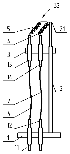
[0021] Such as figure 1 As shown, a dual-filament neutralizer 32 for ion beam equipment includes a flange 1, a pole 2, a bracket 3, a filament A4, a filament B 5, a wire A 6, a wire B 7, an electrode A 11, and an electrode B 12 , electrode C 13, and electrode D 14.

[0022] The flange 1 is made of a metal steel material for fixing the strut 2 and sealing the perforation

[0023] The electrode A 11 and electrode B 12 are installed. The electrode A 11 and the electrode B 12 are insulated from the flange 1

[0024] Edge seal welding.

[0025] The bracket 3 is made of a metal steel material, and is used for fixing the pole 2 through holes and installing the electrod...


PUM

PropertyMeasurementUnit
diameteraaaaaaaaaa

Abstract

The invention discloses a double lamp filament neutralizer for ion beam equipment. The double lamp filament neutralizer for the ion beam equipment comprises a flange, a supporting rod, a bracket, a lamp filament A, a lamp filament B, a wire A, a wire B and four electrodes. As a mode of the neutralizer independent of an ion source is adopted, two lamp filaments are arranged, the neutralizing efficiency of the neutralizer is high, the lamp filaments are not directly bombarded by an ion beam, the service life of the lamp filaments is long, the working efficiency of the complete machine equipmentis high, lamp filament material atoms are not prone to polluting a vacuum chamber and workpieces, and mounting and maintenance are convenient.

Description

technical field [0001] The invention relates to the technical field of ion beams, in particular to a double filament neutralizer for ion beam equipment. Background technique [0002] Ion beam sputtering coating or etching technology provides new technology and new technology for scientific research and production, and provides new technology for a wide range of applications such as thin film integrated circuits, thin film sensors, magnetic thin film devices, and superalloy conductor thin films that are rapidly developing today. technical means. [0003] However, for this type of ion beam sputtering coating or etching equipment, the ion source neutralizer is still installed directly in front of the ion source with a single filament. The advantage of this design is that the neutralizer is completely immersed in the ion beam, and the neutralization efficiency is high. , but the filament of the neutralizer is strongly bombarded by the ion beam, the filament quickly becomes thin...

Claims


Application Information

Patent Timeline
Patent Type & Authority Applications(China)
IPC IPC(8): C23C14/46H01J37/30H01J37/305
Inventor 不公告发明人
Owner BEIJING CHUANGDENENG TECH
Why Eureka
Try Eureka