
Micro-fluidic chip for geological process chemical corrosion study and making method

A microfluidic chip and process chemistry technology, applied in chemical instruments and methods, laboratory containers, laboratory utensils, etc., can solve the problem of hindering multiphase flow movement and material exchange process, Newton rings appearing on the glass surface, chip Reduced production yield and other issues, to achieve the effect of convenient mass production, short preparation time, and high channel production accuracy

Active Publication Date: 2019-06-18
WUHAN UNIV +1
View PDF5 Cites 5 Cited by
  • Summary
  • Abstract
  • Description
  • Claims
  • Application Information

AI Technical Summary

Problems solved by technology

However, limited by the non-optical characteristics of rock and soil, the problem of clear and real-time monitoring of fluid movement in rock-soil pores / cracks and its impact on the surrounding environment has not been resolved, which hinders our deep understanding of pore / crack media Movement and material exchange process of multiphase flow in medium
[0004] At present, the microfluidic chip materials widely used in the fields of biology and medicine mostly use crystalline silicon, glass, quartz and various polymer materials, and the conditions required for the production process are relatively strict, especially when bonding chips. , requires a variety of equipment to assist, such as crystalline silicon, glass and quartz chip bonding requires high temperature (~800°C) and high pressure, and often due to operational technical problems, defects such as Newton rings appear on the glass surface that affect experimental observation, resulting in chips Lower production yield

Method used


Image

  • Micro-fluidic chip for geological process chemical corrosion study and making method
  • Micro-fluidic chip for geological process chemical corrosion study and making method
  • Micro-fluidic chip for geological process chemical corrosion study and making method

Examples


Embodiment Construction

[0018] The present invention will be described in detail through examples below, but the protection scope of the present invention is not limited to the following description. Unless otherwise specified, the experimental methods used are conventional experimental methods; the reagents and materials used can be obtained through commercial channels.

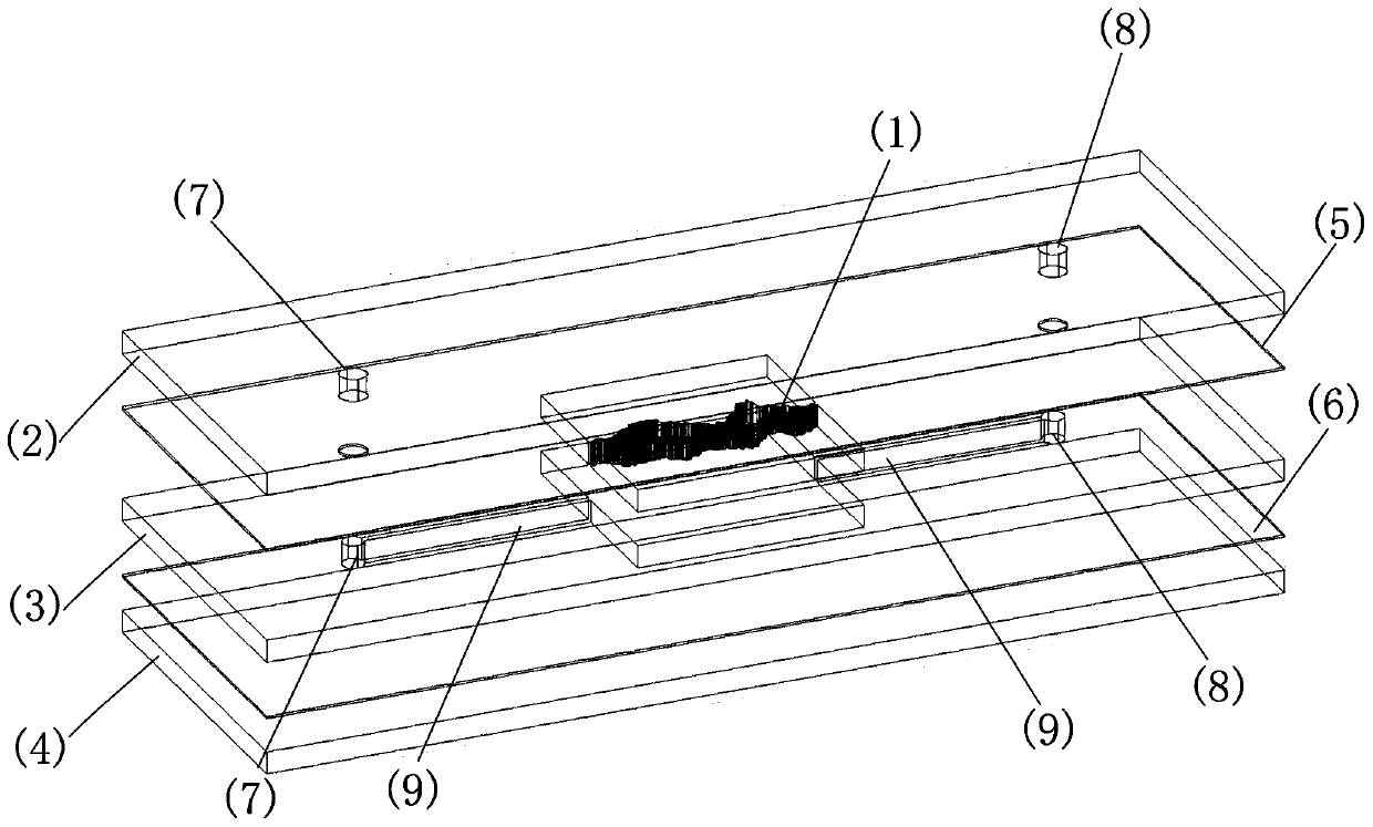
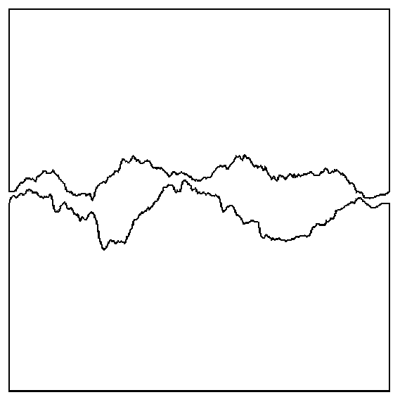
[0019] The microfluidic chip used for chemical dissolution research in geological processes provided by the present invention includes a microfluidic chip main body 1 with microchannels arranged in parallel horizontally, an upper base layer 2, a middle base layer 3, a lower base layer 4, and an upper base layer Layer 5, lower adhesive coating 6; upper base layer 2, upper adhesive coating layer 5, middle base layer 3, lower adhesive layer 6 and lower base layer 4 are arranged horizontally parallel to chip main body 1 from top to bottom, and middle base layer 3 runs through horizontally The chip main body 1 is divided into the upper ...


PUM


Abstract

The invention discloses a micro-fluidic chip for geological process chemical corrosion study and a making method. The making method includes following steps: preparing a micro-fluidic chip body, etching upper, middle and lower base layer channels, and bonding and encapsulating upper, middle and lower base layers with the micro-fluidic chip body to finally obtain the micro-fluid chip. The micro-fluidic chip body can be made of easy-to-get universal materials like sodium chloride crystal and tested rock slices, silicate glass slide having transparent characteristic or organic glass of epoxy resin is adopted as upper and lower substrates, the micro-fluidic chip can be prepared at normal temperature and normal pressure generally, and total making time is 2-3h. The method has the advantages ofhigh channel making accuracy, simple chip encapsulating process, short preparation time, flexible application and convenience for mass production, and the method expands micro-fluidic technology fromthe field of biomedicine to subjects like geophysics and energy environment.

Description

technical field [0001] The invention belongs to the technical field of microfluidic control, and specifically refers to a microfluidic chip used for chemical dissolution research in geological processes and a manufacturing method. Background technique [0002] There are often multi-component and multi-phase fluids (such as air, water, and non-aqueous pollutants, etc.) in the deep porous fractured rock mass and near-surface unsaturated rock-soil pores. The dynamical movement characteristics between them and the material exchange between rock and soil have great influence on the research of shale oil (gas) exploitation, CO 2 Geological storage and groundwater pollutant transport are of great significance. However, limited by the non-optical characteristics of rock and soil, the problem of clear and real-time monitoring of fluid movement in rock-soil pores / cracks and its impact on the surrounding environment has not been resolved, which hinders our deep understanding of pore / c...

Claims


Application Information

Patent Timeline
Patent Type & Authority Applications(China)
IPC IPC(8): B01L3/00
Inventor 胡冉武东生陈益峰周晨星王一凡魏鹳举赵先进
Owner WUHAN UNIV
Learn More