
Three-section ceramic valve

A three-stage, ceramic valve technology, used in sliding valves, valve details, valve devices, etc., can solve problems such as poor impact resistance, overcome brittleness, improve sealing effect, and facilitate rapid assembly and installation.

Pending Publication Date: 2019-06-18
郑州鼎盛新技术有限公司
View PDF0 Cites 0 Cited by
  • Summary
  • Abstract
  • Description
  • Claims
  • Application Information

AI Technical Summary

Problems solved by technology

The present invention improves the overall structure of the valve body into a three-section combined valve body on the basis of the traditional gate valve, which greatly facilitates the grinding of ceramic valve seats and the rapid assembly and installation of ceramic sealing parts after processing, and improves the The sealing effect avoids the single force of ceramics. While giving full play to the advantages of high hardness, wear resistance and corrosion resistance of ceramic valves, it also overcomes the defects of high brittleness and poor impact resistance of ceramic materials, greatly improving the service life of valves, especially Suitable for installation in the operating environment of wear-resistant and corrosion-resistant slag paddle systems

Method used


Image

  • Three-section ceramic valve
  • Three-section ceramic valve

Examples


Embodiment 1

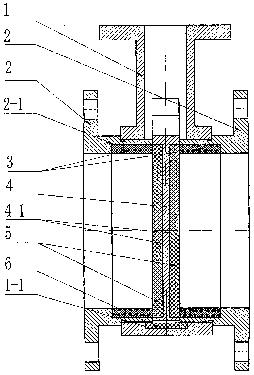
[0022] Such as figure 1 As shown, a three-section ceramic valve in Embodiment 1 includes a three-section combined valve body and a ceramic gate inserted in the flow channel of the valve body; the ceramic gate is composed of a gate base (4) and an embedded The gate ceramics (5) installed in the gate grooves (4-1) on both surfaces of the gate base body are composed of (the ceramic gate is a self-sealing parallel gate, and the two sealing surfaces are parallel to each other, that is, the The gate ceramics (5) are embedded in the gate grooves (4-1) on both surfaces of the gate base (4), which can resist the erosion and wear of the gate base by the medium when the valve adjusts the flow rate); The combined valve body is composed of two valve seats (2) which form the flow channel of the valve body after the buckle arrangement, and the valve body base (1) which is sleeved and connected on the outer surface of the proximal end of the two valve seats (2) (the two valve seats (2) The t...

Embodiment 2

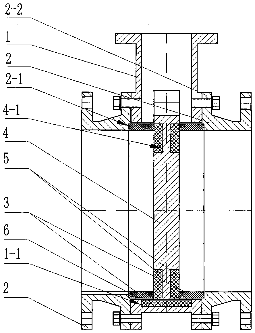
[0028] Such as figure 2 As shown, the difference between embodiment two and embodiment one is:

[0029] The gate ceramic (5) described in the second embodiment has a circular structure; the gate grooves (4-1) located on both surfaces of the gate base (4) are circular grooves; the gate grooves The shape and specification of (4-1) match the shape and specification of the gate ceramics (5).

[0030]In the second embodiment, the proximal ends of the two valve seats (2) are connected to the valve body substrate (1) through flanges and bolts; the outer surfaces of the proximal ends of the two valve seats (2) are all along the diameter A boss flange (2-2) protrudes outwards, and a bolt hole is processed on the boss flange (2-2), and is connected with the boss flange ( 2-2) Threaded holes are processed at the fitting parts.

[0031] Concrete usage of the present invention is as follows:

[0032] Firstly, the gate ceramics (5) are embedded and fixed in the gate grooves (4-1) on bo...


PUM


Abstract

The invention discloses a three-section ceramic valve, and relates to the field of valves. A deslagging valve comprises a three-section combination valve body and a ceramic gate plate which is inserted into a valve body flow channel; the ceramic gate plate consists of a gate plate substrate and gate plate ceramic which is embedded into the gate grooves in the two surfaces of the gate plate substrate; the combination valve body consists of two valve seats which form the valve body flow channel after being arranged by buckling and closing and a valve body substrate which is sleeved and connectedat the outer surfaces of the near ends of the two valve seats; valve seat ceramic is embedded into each inner cavity surface of the near ends of the two valve seats; a sealing end surface of the valve seat ceramic closely fits the sealing surface of the gate plate ceramic to form a sealing pair; and bottom ceramic is embedded into a combination part between the bottom of the ceramic gate plate and the inner cavity surface of the valve body substrate. According to the three-section ceramic valve, grinding and machining of the ceramic valve seats and quick assembling and mounting of processed ceramic sealing components are greatly facilitated; the sealing effect is avoided; individual stress of the ceramic is avoided; and the three-section ceramic valve has the advantages of high hardness,wear resistance, corrosion resistance and long service life.

Description

technical field [0001] The invention belongs to the technical field of valves, and in particular relates to a three-stage ceramic valve, which is especially suitable for being installed in the operating environment of wear-resistant and corrosion-resistant slag paddle systems. Background technique [0002] As an important pipeline accessory, valves are widely used in production and living fields. The service life of the valve mainly depends on the life of the sealing surface, because most of the valves are scrapped due to the damage of the sealing surface. In the past 20 years, with the development of engineering ceramic materials, people have introduced engineering ceramic materials with high hardness, wear resistance and corrosion resistance into the valve industry, using engineering ceramic materials as valve sealing materials, greatly improving the service life of valves (e.g. gate valves for slurry systems). However, a new problem appeared in the process of use: due t...

Claims


Application Information

Patent Timeline
IPC IPC(8): B24B19/22B24B41/06F16K3/02F16K3/30F16K3/314F16K27/04
Inventor 马俊峰谢民
Owner 郑州鼎盛新技术有限公司
Learn More