A multi-layer plate frame floating photocatalytic water purification device and its application

A water purification device and photocatalysis technology, which is applied in the direction of light water/sewage treatment, oxidized water/sewage treatment, reduced water/sewage treatment, etc., can solve the problems of low photocatalysis efficiency and low light utilization efficiency, and achieve the goal of ensuring light receiving area, reduce waste, and ensure stable operation

Active Publication Date: 2021-08-27
SHANDONG UNIV
View PDF8 Cites 1 Cited by
  • Summary
  • Abstract
  • Description
  • Claims
  • Application Information

AI Technical Summary

Problems solved by technology

[0006] Aiming at the deficiencies of the existing technology, especially the existing photocatalytic sewage treatment device only responds to a single light zone of sunlight, and the light utilization efficiency is low, the present invention provides a multi-layer plate and frame floating photocatalytic water purification device
The invention is simple in structure, easy to use, effectively solves the problem of low photocatalytic efficiency in water, and makes it maximize the purification effect

Method used


Image

  • A multi-layer plate frame floating photocatalytic water purification device and its application
  • A multi-layer plate frame floating photocatalytic water purification device and its application

Examples


Embodiment 1

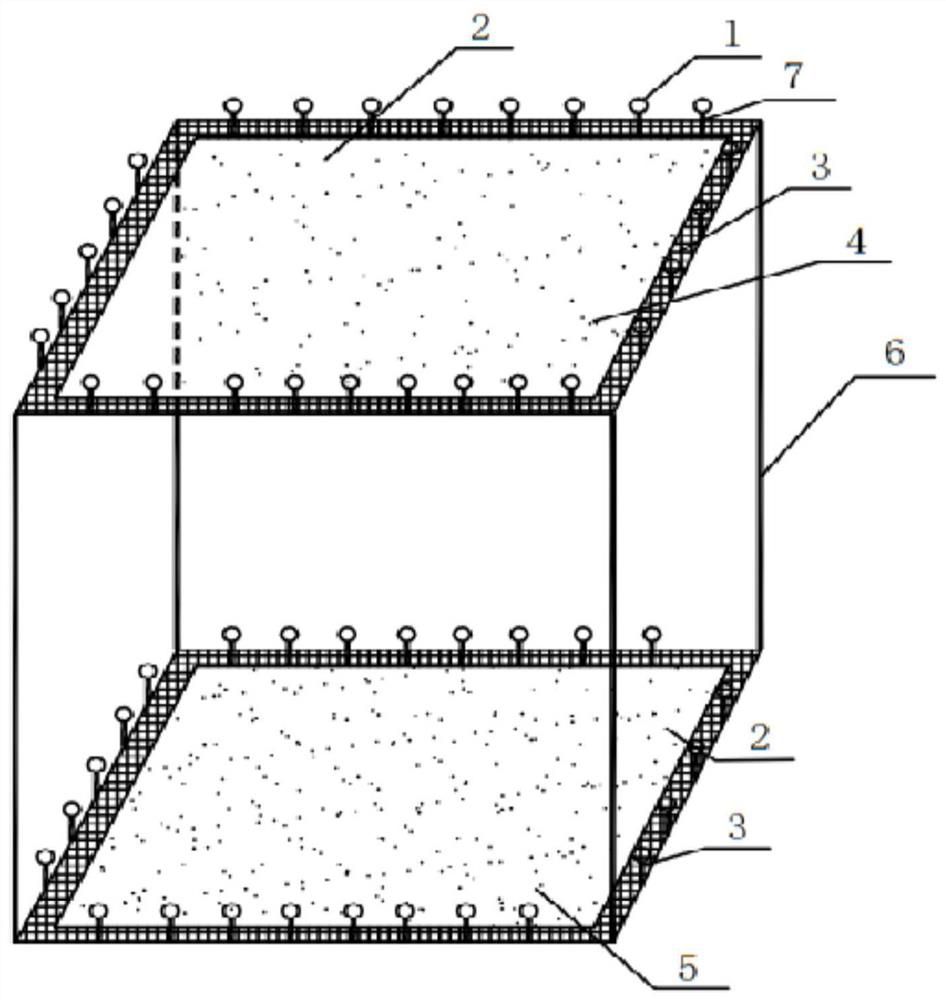
[0036] Such as figure 1 , 2 As shown, a multi-layer plate frame type floating photocatalytic water purification device includes a visible light catalytic unit and an ultraviolet photocatalytic unit, and the visible light catalytic unit and the ultraviolet photocatalytic unit are connected by connecting ribs 6; The catalytic unit includes a visible photocatalytic layer 4, and the ultraviolet photocatalytic unit includes a layer of ultraviolet photocatalytic layer 5;

[0037] The visible photocatalytic layer 4 includes a base fabric 2 and a plate frame 3, the base fabric 2 is loaded with a carbon nitride visible light catalytic material, and the base fabric 2 is fixedly arranged on the plate frame 3;

[0038] The ultraviolet photocatalytic layer 5 includes another base fabric 2 and another plate frame 3, the other base fabric 2 is loaded with titanium dioxide ultraviolet photocatalytic material, and the other base fabric 2 is fixedly arranged on the other plate frame 3;

[003...

Embodiment 2

[0043] As described in Example 1, the difference is:

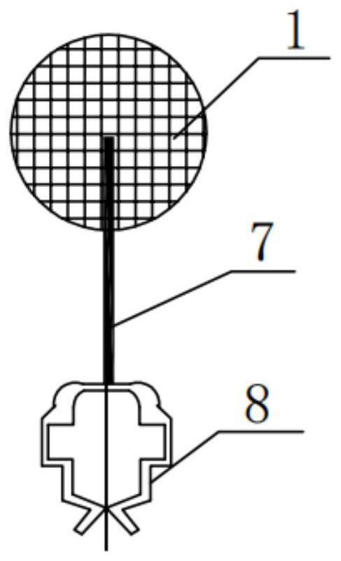
[0044] The plate frame 3 is only arranged around the base fabric 2 . This setting is beneficial to reduce the weight of the plate frame 3 itself, while protecting the base fabric 2 at the same time. The floating assist device 1 is a floating rod, which is fixedly connected to the plate frame 3 by binding the floating rod 7 with cable ties.

[0045] In this embodiment, the mesh gap between the base fabric 2 and the frame 3 in the visible photocatalytic layer 4 is 1 cm, and the mesh gap between the base fabric 2 and the frame 3 in the ultraviolet photocatalytic layer 5 is 0.4 cm. The distance between the visible photocatalytic layer 4 and the ultraviolet photocatalytic layer 5 is 20 cm.

Embodiment 3

[0047] As described in Example 1 or 2, the difference is:

[0048] A baffle is vertically arranged around the said plate frame 3, and the baffle is vertically arranged with the plate frame, and the height of the baffle is 1 cm.

[0049] In this embodiment, the mesh gap between the base fabric 2 and the frame 3 in the visible photocatalytic layer 4 is 1.5 cm, and the mesh gap between the base fabric 2 and the frame 3 in the ultraviolet photocatalytic layer 5 is 0.7 cm. The distance between the visible photocatalytic layer 4 and the ultraviolet photocatalytic layer 5 is 40 cm.


PUM

PropertyMeasurementUnit
cover factoraaaaaaaaaa

Abstract

The invention relates to a multi-layer plate and frame type floating photocatalytic water purification device and its application, comprising a visible light catalytic unit and an ultraviolet photocatalytic unit, the visible light catalytic unit and the ultraviolet photocatalytic unit are connected by connecting ribs; the visible light catalytic unit includes multiple A visible photocatalytic layer, the ultraviolet photocatalytic unit includes multiple ultraviolet photocatalytic layers, the visible photocatalytic layer and the ultraviolet photocatalytic layer both include a base fabric and a frame, the base fabric is loaded with visible light and ultraviolet photocatalytic materials respectively, and the base fabric is fixedly set On the plate frame, the visible photocatalytic unit is provided with a flotation aid. The invention utilizes a variety of photocatalytic materials to improve the utilization rate of sunlight; it can also ensure sufficient contact between pollutants and photocatalytic materials, and effectively utilize photocatalytic reduction and photocatalytic oxidation to accelerate the removal of pollutants; the plate and frame can When the water flow increases sharply, it plays a good anti-water flow effect, relieves the rupture of the fabric, and ensures the light-receiving area of ​​the membrane device.

Description

technical field [0001] The invention relates to the field of water environment treatment, in particular to a multilayer plate and frame floating photocatalytic water purification device and its application. Background technique [0002] In recent years, due to the continuous acceleration of industrial development, a large amount of sewage and waste water has been discharged into rivers and lakes, and my country's water environment has problems such as low dissolved oxygen, low transparency, and high nitrogen and phosphorus pollution. More and more attention has been paid to the restoration technology aimed at removing pollutants in the water body and improving the quality of the river water environment. Moreover, persistent refractory pollutants such as antibiotics and estrogens are frequently detected in typical environmental water bodies (even including drinking water and groundwater). Threats to aquatic ecological security and human health. Such pollutants have low conc...

Claims


Application Information

Patent Timeline
Patent Type & Authority Patents(China)
IPC IPC(8): C02F1/30C02F1/32C02F1/70C02F1/72
Inventor 徐世平张启亮林妙丽刘美娜滕敏岳钦艳
Owner SHANDONG UNIV
Why Eureka
Try Eureka