
Simple and compact wide-stop-band filtering patch antenna

A patch antenna and wide stop band technology, applied in the direction of antenna, antenna grounding device, antenna grounding switch structure connection, etc., to achieve the effect of compact structure, wide bandwidth, and reduced volume

Active Publication Date: 2019-06-18
SOUTH CHINA UNIV OF TECH
View PDF10 Cites 12 Cited by
  • Summary
  • Abstract
  • Description
  • Claims
  • Application Information

AI Technical Summary

Problems solved by technology

The design methods of filter antennas are mainly divided into two categories: one method is the integrated design of the filter and the antenna, and the antenna is used as the last stage of the filter to resonate, but there is still insertion loss in the system

Method used


Image

  • Simple and compact wide-stop-band filtering patch antenna
  • Simple and compact wide-stop-band filtering patch antenna
  • Simple and compact wide-stop-band filtering patch antenna

Examples


Embodiment Construction

[0028] The present invention will be described in further detail below in conjunction with the embodiments and the accompanying drawings, but the embodiments of the present invention are not limited thereto.

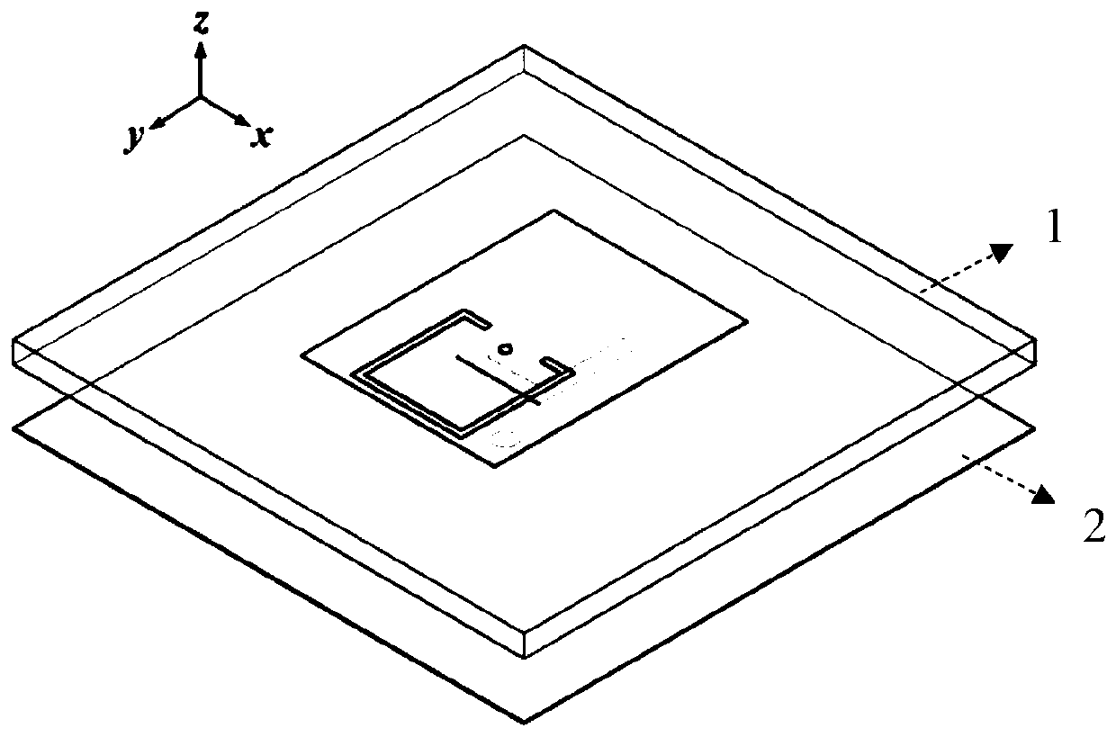
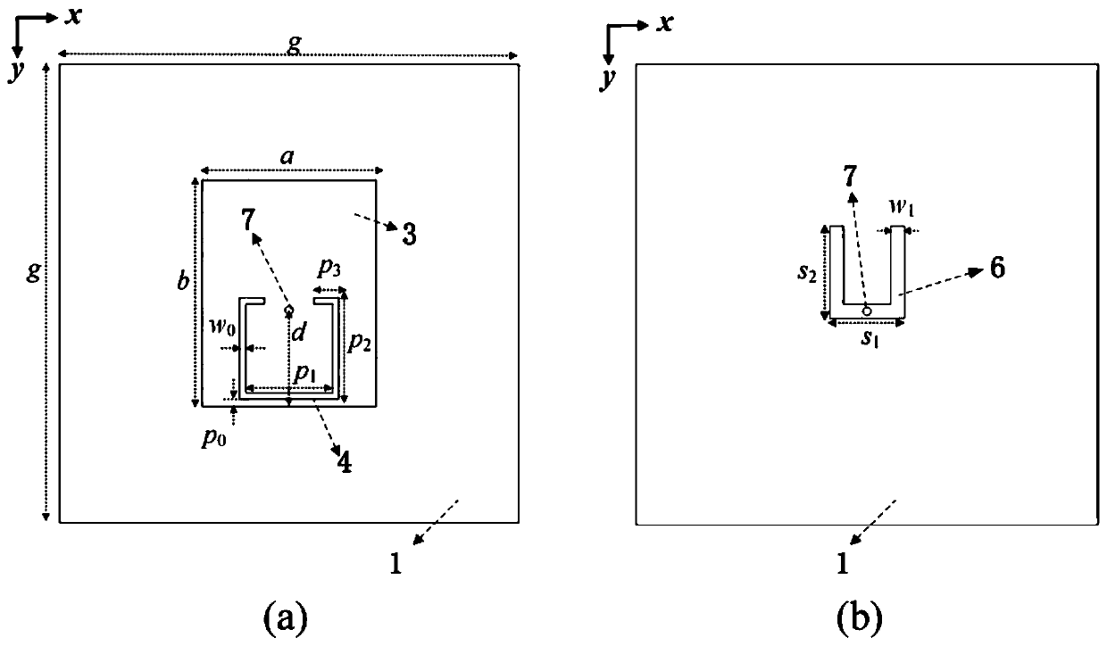
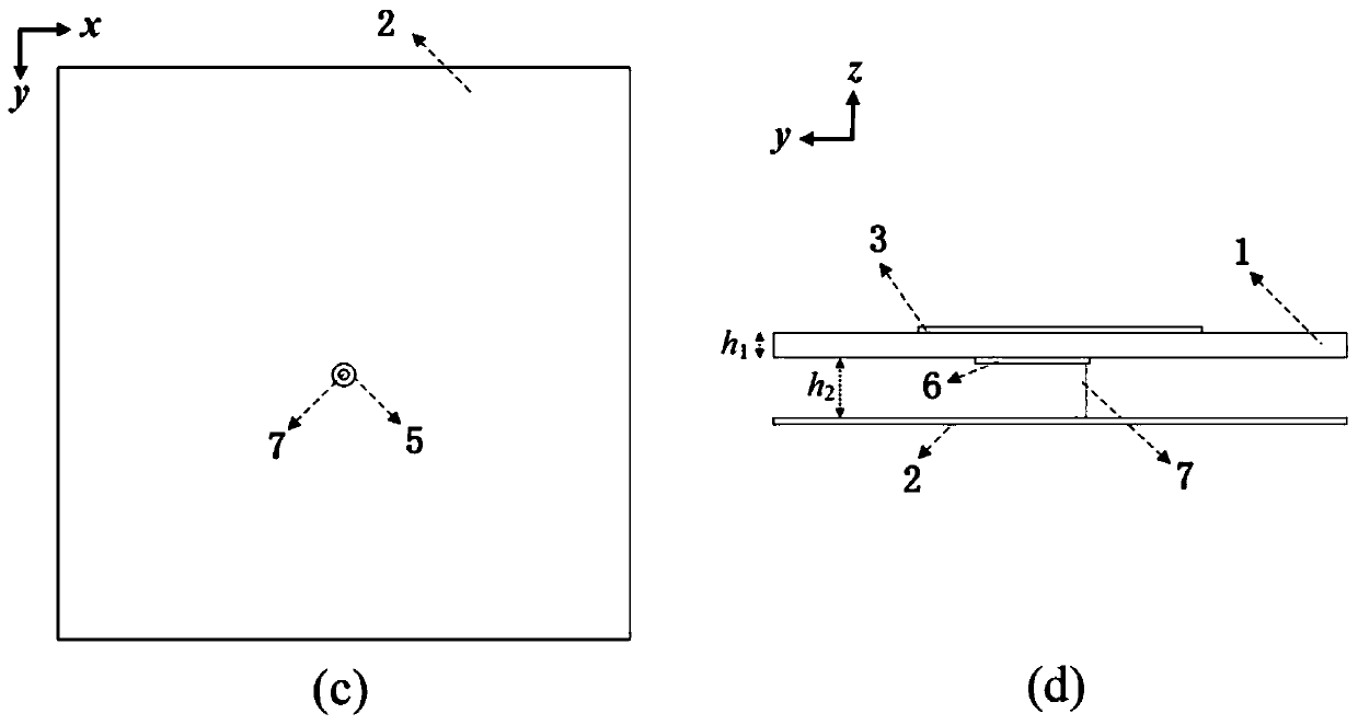
[0029] Such as figure 1 , figure 2 As shown in (a) to 2(d), a simple and compact wide stopband filter patch antenna includes a rectangular dielectric substrate 1, a metal floor 2, and a metal probe 7. The dielectric substrate 1 and the metal floor 2 are up and down Arranged at intervals, the upper surface of the dielectric substrate 1 is centered with a metal rectangular radiation patch 3, and the radiation patch 3 is provided with an open ring-shaped gap 4; the lower surface of the dielectric substrate 1 is provided with a metal U-shaped Branch 6, the opening direction of the open ring-shaped gap 4 and the U-shaped branch 6 are consistent and both are symmetrical structures about the y-direction axis of the dielectric substrate 1; the metal probe 7 is vertically arran...


PUM


Abstract

The invention discloses a simple and compact wide-stop-band filtering patch antenna. The simple and compact wide-stop-band filtering patch antenna comprises a dielectric substrate and a metal floor which are arranged at an interval up and down and a metal probe; a radiation patch is arranged in the middle of the upper surface of the dielectric substrate; the radiation patch is provided with an open ring-shaped gap; a U-shaped branch is arranged on the lower surface of the dielectric substrate; the open ring-shaped gap and the U-shaped branch are consistent in opening direction and are both ofa symmetrical structure about a y-directional central axis of the dielectric substrate; one end of the metal probe is concentric with a round hole formed on the metal floor to form a coaxial feeding structure; and the other end of the metal probe is connected with the radiation patch after sequentially passing through an intersection of the metal U-shaped branch and the y-directional central axisand the dielectric substrate. The simple and compact wide-stop-band filtering patch antenna is simple in structure; a volume of a radio frequency front end can be greatly reduced and no additional insertion loss is generated; filtering performance can be implemented under a compact high-gain structure; and the simple and compact wide-stop-band filtering patch antenna is easy to machine, low in cost, small in volume and more suitable for planar antenna array design and large-scale production.

Description

technical field [0001] The invention relates to a filter antenna, in particular to a simple and compact wide stopband filter patch antenna. Background technique [0002] With the development of modern wireless communication technology, the communication system tends to be miniaturized, integrated and multifunctional. Due to the mature development of large-scale integrated circuit technology and semiconductor IC technology, the miniaturization design of microwave active circuits can be realized, and single-chip multi-functional integration can be realized by using packaging technology. However, for microwave passive circuits, especially for the design of RF front-end devices, their working mechanism is limited by physical size and environmental factors. Difficulty of transformation. [0003] In wireless communication systems, devices such as filters and antennas are essential, and their functions are mainly to realize signal selection, filter out noise outside the frequency...

Claims


Application Information

Patent Timeline
IPC IPC(8): H01Q1/38H01Q1/48H01Q1/50H01Q15/00
Inventor 杨琬琛张迎琪车文荃薛泉廖绍伟陈璐
Owner SOUTH CHINA UNIV OF TECH
Learn More