
Fuel oil dilute oxygen combustion system

An oxy-combustion system and fuel oil technology, applied in the direction of using a variety of fuel combustion, burners, combustion methods, etc., can solve the problems of short duration, unstable combustion, etc., to enhance uniformity and stability, and complete atomization. Effect

Inactive Publication Date: 2019-06-21
XIANGTAN ZHILIAN TECH MATASTASIS PROMOTE CO LTD
View PDF0 Cites 2 Cited by
  • Summary
  • Abstract
  • Description
  • Claims
  • Application Information

AI Technical Summary

Problems solved by technology

However, the non-obvious flame state maintained by many dilute oxygen tests does not last long, the combustion is unstable, and the fuel used is mostly limited to gaseous fuels such as natural gas

Method used


Image

  • Fuel oil dilute oxygen combustion system
  • Fuel oil dilute oxygen combustion system
  • Fuel oil dilute oxygen combustion system

Examples


Embodiment Construction

[0025] The biomass pyrolysis experimental furnace provided by the present invention will be further described in detail and completely below in conjunction with the examples. The embodiments described below are exemplary only for explaining the present invention and should not be construed as limiting the present invention.

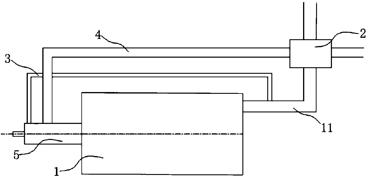
[0026] Such as figure 1 As shown, the present invention includes a furnace body 1 , a heat exchanger 2 , a flue gas return pipe 3 , a gas-supporting pipe 4 and a burner body 5 . The burner body 5 is installed on one end of the furnace body 1, the other end of the furnace body 1 is provided with a flue gas discharge pipe 11, the flue gas discharge pipe 11 is connected to the heat-absorbing end of the heat exchanger 2, and the heat-releasing end of the heat exchanger 2 is connected to the gas-supporting pipe 4. The other end of the gas-supporting pipe 4 is connected to the burner body 5 . The flue gas return pipe 2 is a branch pipe of the flue gas dischar...


PUM


Abstract

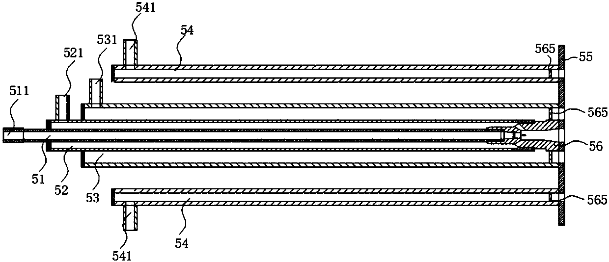
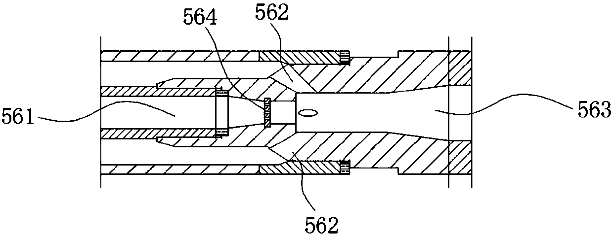
The invention discloses a fuel oil dilute oxygen combustion system comprising a furnace body, a heat exchanger, a smoke backflow pipe, a combustion supporting gas pipe and a combustor body. The combustor body is installed on the furnace body. The two ends of the smoke backflow pipe communicate with the combustor body and a smoke discharge pipe correspondingly. The two ends of the combustion supporting gas pipe communicate with the combustor body and the heat exchanger. The heat exchanger is further connected with the smoke discharge pipe. The combustor body is provided with a fuel oil pipe, acompressed gas pipe, a smoke pipe and multiple combustion supporting pipes. The fuel oil pipe, the compressed gas pipe, the smoke pipe and the combustion supporting pipes are all fixed to an installation plate. A fuel oil atomization mixer is arranged at the end, close to the installation plate, of the fuel oil pipe. The fuel oil atomization mixer is provided with a fuel oil hole and multiple compressed gas holes. The fuel oil hole and the compressed gas holes all communicate with a mixing cavity. The fuel oil hole communicates with the fuel oil pipe, the section of the fuel oil hole firstly shrinks and then keeps unchanged in the fuel oil flowing direction, and a flow distributor is arranged at the narrowest position of the section. The compressed gas holes communicate with the compressedgas pipe, and the section of each compressed gas hole shrinks in the compressed gas direction. Spinning disks are arranged at the positions, close to the installation plate, of the smoke pipe and thecombustion supporting pipes. The fuel oil dilute oxygen combustion system is good in atomized fuel oil, smoke and combustion supporting gas mixing, stable in flameless combustion and capable of saving energy.

Description

technical field [0001] The invention relates to a fuel oil lean oxygen combustion system, which belongs to the field of combustion systems. Background technique [0002] Burners are key components for organizing air flow, heat transfer and combustion in boilers and high-temperature furnaces. Traditional flame-concentrated burners usually set the fuel and air inlet positions in a centralized manner. After the fuel and air flow out of the burner, they intersect at a very close position, showing concentrated flames, small flame volume, obvious local high-temperature areas, and small flames. High-intensity heat release in the area and uneven heating are not conducive to the production of processes that require uniform heating, and local high temperatures give thermal NO x The formation creates conditions that reduce the service life of the lining. [0003] In order to meet the demand for uniform heating technology in smelting and other industries, research on dilute oxygen com...

Claims


Application Information

Patent Timeline
Patent Type & Authority Applications(China)
IPC IPC(8): F23C5/08F23C9/00F23D11/10F23D11/44
CPCY02E20/34
Inventor 不公告发明人
Owner XIANGTAN ZHILIAN TECH MATASTASIS PROMOTE CO LTD
Learn More