Superposition state vortex light-based object rotation direction detecting device

A technology of rotation direction and detection device, which is applied to devices using optical methods, measurement devices, speed/acceleration/impact measurement, etc., can solve the problems of inability to effectively obtain the rotation direction of objects, and achieve novel technology, convenient use, and easy control Effect

Inactive Publication Date: 2019-06-21
PLA PEOPLES LIBERATION ARMY OF CHINA STRATEGIC SUPPORT FORCE AEROSPACE ENG UNIV
View PDF12 Cites 19 Cited by
  • Summary
  • Abstract
  • Description
  • Claims
  • Application Information

AI Technical Summary

Problems solved by technology

[0015] The problem solved by the technology of the present invention is: aiming at the problem that the existing non-contact detection device for rotating objects can only obtain the information of the rotation rate of the object but cannot effectively obtain the rotation direction of the object, a device that can effectively measure the rotation direction of the object is designed

Method used


Image

  • Superposition state vortex light-based object rotation direction detecting device
  • Superposition state vortex light-based object rotation direction detecting device
  • Superposition state vortex light-based object rotation direction detecting device

Examples


Embodiment Construction

[0042] specific implementation plan

[0043] In the present invention, the superposition vortex beam is used as the detection carrier, and the specific implementation steps are as follows:

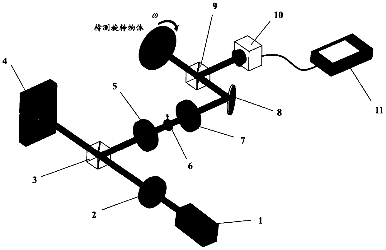
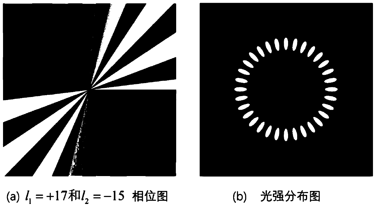
[0044] Firstly, a laser beam with a wavelength of 632.8 nm is generated by a laser (1), modulated by a polarizer (2), and then becomes horizontally polarized light, and then irradiates the spatial light modulator through a dichroic prism. The spatial light modulator is loaded with pre-prepared topological charges of l 1 and l 2 The vortex optical hologram, where l 1 and l 2 The sign is opposite and the size is different. The hologram used and the superposition state spot produced by it are as follows image 3 shown.

[0045] Next, irradiate the generated superposition vortex beam onto the surface of the rotating object, use the photoelectric converter to receive and convert the scattered beam on the surface of the object, and finally import the electrical signal into the oscilloscope ...


PUM


Abstract

The invention relates to a superposition state vortex light-based object rotation direction detecting device. The main components of the device include a He-Ne laser, a polarizer, a beam splitting prism, a spatial light modulator, a 4f filtering system, a plane mirror, a photoelectric detector and a micro oscilloscope. Laser generated by the laser is transmitted through the polarizer and then irradiates the spatial light modulator; the spatial light modulator is loaded with a superposition state beam hologram of which topological charges have opposite signs and have unequal values, so as to generate superposition state vortex light; the 4f filtering system screens out first-order diffracted light, and the first-order diffracted light irradiates a rotating object, and the photoelectric detector receives scattered light and performs spectrum analysis so as to obtain a frequency shift value; a rotation speed is added to the hologram, and then, signal acquisition is performed; and two frequency shift values obtained at two different times can be compared with each other, so that the rotation speed and rotation direction information of the object can be obtained. The device is simple instructure and can fully obtain various kinds of information related to the rotation of the object.

Description

technical field [0001] The invention mainly relates to the fields of optics, physics, photoelectric conversion, and signal detection, especially technical methods such as phase modulation and beat frequency detection of light beams. [0002] technical background [0003] The technical background of the invention is mainly based on the rotational Doppler effect. The classic Doppler effect (LDE) is caused by the linear relative velocity between the object and the wave source. Its technology is mature and its application field is wide. For a system using light beams as the detection wave source, the difference Δf between the frequency of light emitted by the light source and the frequency received by the moving object is: [0004] [0005] where f is the frequency of the detection light source, v o is the moving speed of the object relative to the light source, and c is the speed of light. [0006] When the moving direction of the object is not collinear with the beam prop...

Claims


Application Information

Patent Timeline
Patent Type & Authority Applications(China)
IPC IPC(8): G01P3/36G01P13/04
Inventor 任元邱松刘通王琛李智猛陈琳琳陈晓岑邵琼玲
Owner PLA PEOPLES LIBERATION ARMY OF CHINA STRATEGIC SUPPORT FORCE AEROSPACE ENG UNIV
Why Eureka
Try Eureka