Process for producing gasoline components

a gasoline and process technology, applied in the direction of hydrocarbon preparation catalysts, organic chemistry, chemistry apparatus and processes, etc., can solve the problems of limited alkylate production, high cost, and questionable etherification

Active Publication Date: 2008-02-12
NESTE OIL OY
View PDF18 Cites 11 Cited by
  • Summary
  • Abstract
  • Description
  • Claims
  • Application Information

AI Technical Summary

Benefits of technology

[0012]It is an object of the present invention to eliminate problems of prior art and to provide a novel process for the production of gasoline components from an olefinic C3-C7 hydrocarbon stream. In particular, it is an object of the invention to provide a process for dimerizing olefinic hydrocarbons.
[0021]A less obvious, but in a large-scale operation very significant advantage is related to side products of the dimerization process. It should be noted that in normal refinery streams there is a large amount of linear olefins in addition to isoolefins. E.g. in a typical C4 stream from a fluidized catalytic cracking unit (FCC) there is approximately 15% of isobutene and 45% of 1-butene, cis-2-butene and trans-2-butene. When such a stream is used as a feedstock for isoolefin dimerization, besides isoolefin dimers, a significant amount of codimers between isoolefin and linear olefins will be produced. E.g. in dimerization of the above-mentioned FCC C4 stream, as much as up to 15 to 25% of the total dimer product may consist of said codimers. Thus, the amount and quality of these side products is very important for the process economy. Usually the codimers formed from isoolefin and 2-olefins are more branched and have thereby a higher octane number than codimers formed from 1-olefins. E.g. when isobutene and 1-butene form codimers, the typical products are methylheptenes and dimethylhexenes, whereas codimers formed from cis-2-butene and trans-2-butene with isobutene are mainly trimethylpentenes having essentially higher octane numbers. Thus, the present invention makes it possible to utilize even those linear olefins, which have not reacted during isomerisation, for the production of gasoline grade olefins after dimerization.
[0023]Now, besides causing rearrangement of carbon atoms of the molecule, the skeletal isomerization gives rise to double bond isomerization, as well, thus allowing the ratio of 1-olefins to 2-olefins to change towards equilibrium, thus improving the overall product quality of the dimerization step.
[0024]Another surprising benefit results from the fact that the catalyst used in isoolefin dimerization must be considerably more active than in etherification. Thus, there is a danger of formation of unwanted side products, such as polymers. In dimerization the catalyst is more vulnerable to many catalyst poisons than in etherification. For example butadiene and certain basic nitrogen compounds form a significantly more serious threat than in case of etherification. When a skeletal isomerization step is performed before the dimerization step, these catalyst poisons do not pose a threat to the process. This is due to the fact that poisons are adsorbed or reacted on skeletal isomerization catalyst and can be removed by regeneration. When cleaner feeds are conducted to dimerization, the lifetime of the dimerization catalyst is significantly increased. This means savings in the running cost of the process.
[0025]Moreover, the heat integration between isomerization and dimerization is possible because dimerization reactors operate at temperatures sufficient for vaporizing the skeletal isomerization feed. This also means savings in process costs and an ease of operation and process design.

Problems solved by technology

Moreover, isoolefins tend to be too reactive in alkylation and they therefore react readily to yield unwanted side products.
Finally, the total amount of olefins present in the feed stream tends to be higher than the amount of available isoparaffins and any alkylate production is limited by the amount of isoparaffins in the feed.
However, in recent times, etherification has become questionable because of the water pollution caused by MTBE released from leaking gasoline storage tanks.
Dehydrogenation is an expensive process and requires a costly investment in the process design and equipment.
This also is costly.
None of the above processes provides an integral process for producing from a fresh olefinic feedstock gasoline grade components, which meet present standards and requirements.

Method used


Image

  • Process for producing gasoline components
  • Process for producing gasoline components
  • Process for producing gasoline components

Examples


example 1

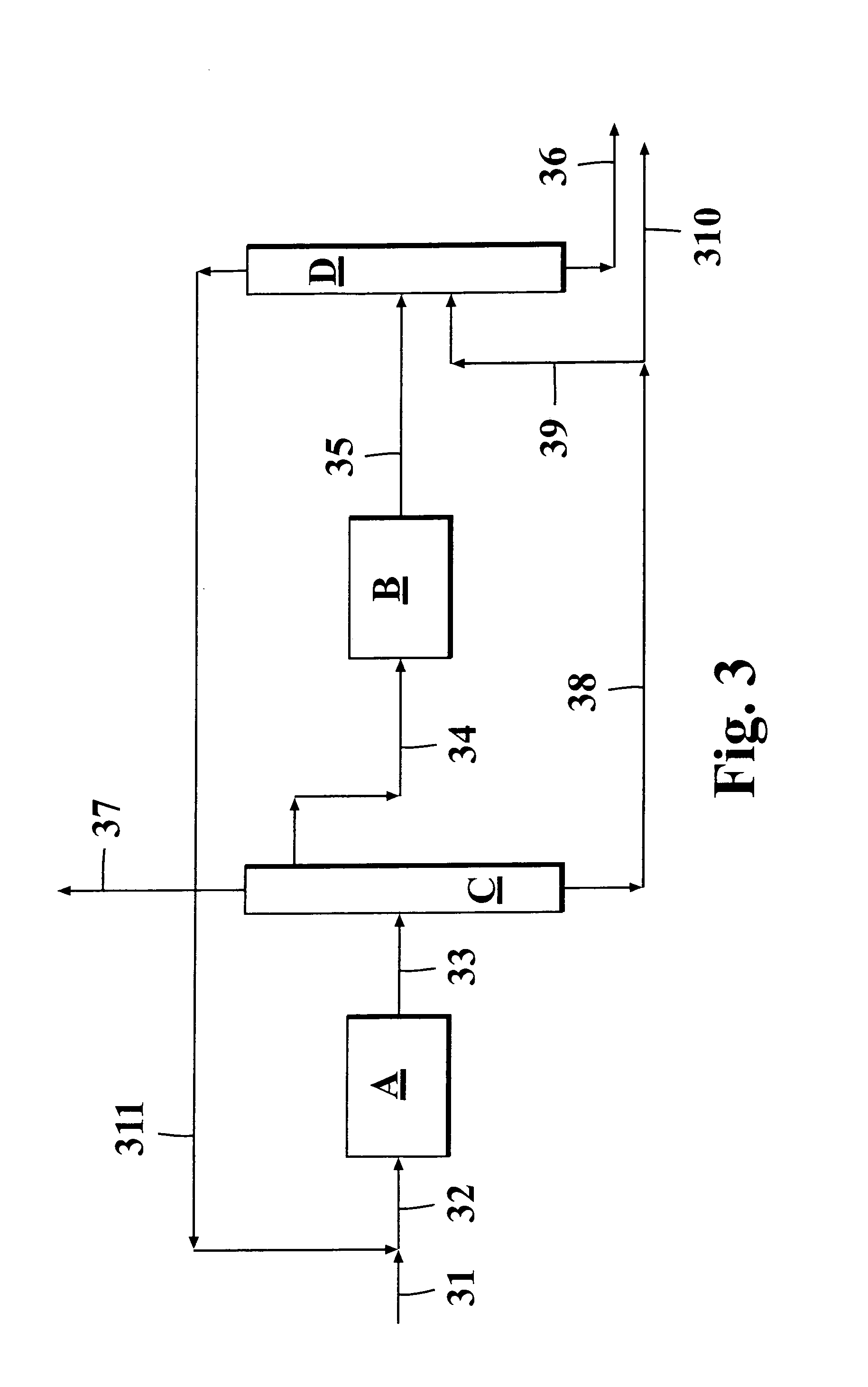
[0069]The process configuration according to FIG. 3 was simulated for producing isoolefin dimers from a hydrocarbon feed containing C4 hydrocarbons. The system has been optimized in order to get the amount of isobutane and butanes in flow leaving the unit to be equal.

[0070]Example 1 presents a system where the combination of skeletal isomerization and dimerization are used for producing an optimal feed for alkylation besides of producing dimer itself. In this case feed 31 is combined with the recycled C4 fraction 311 and the combined stream 32 is conducted to the skeletal isomerization unit A. The resulting stream 33 is conducted to a C4 splitter B, which is mainly intended to enrich the alkylation feed in respect of the higher boiling cis-2-butene and trans-2-butene, which are especially suited for alkylation feedstock. Moreover, from the top of this column is taken a C3 stream 37 in order to prevent their accumulation to the recycle. This column requires significant reboiler duty ...

example 2

[0073]The process for producing isoolefin dimers from a hydrocarbon flow containing C4 hydrocarbons was simulated using a process configuration according to FIG. 4.

[0074]Example 2 presents system where skeletal isomerization and dimerization are connected in a simpler manner. The mixed C4-feed 41 is connected with the recycle C4-stream 49 and conducted to the skeletal isomerization unit A. The isomerized stream 43 is conducted to the dimerization unit B. The dimerized product is further conducted to the recycle column C. This column separates dimer product and the necessary amount of the unreacted C4's from the dimerization effluent as bottom product 45. The C4 recycle stream is taken as side draw 49 and C3s are removed from the recycle via the distillate of column C. The bottom product of column C, stream 45 is further divided in column D into dimer product 46 and C4 raffinate stream 47. The conversion to dimers can be optimized by adjusting the recycle stream 49. The advantage of ...

example 3

[0077]The process for producing isooctane from a hydrocarbon flow containing isobutene was simulated using a process configuration according to FIG. 5.

[0078]Example 3 presents a system where the C4 feed stream 51 is first conducted to the skeletal isomerization unit A. The effluent of isomerization is combined with the C4 recycle stream 59 and the combined stream 53 is conducted to the dimerization unit B. The effluent of the dimerization unit 54 is conducted to the recycle column C. This column separates dimer product and the necessary amount of the unreacted C4's from the dimerization effluent as bottom product 55. The C4 recycle stream is taken as side draw 59 and C3's are removed from the recycle via the distillate of column C. The bottom product of column C, stream 55 is further splitted in column D into dimer product 56 and C4 raffinate stream 57. The advantage of this system is that the skeletal isomerization unit can be made essentially smaller that in the two previous cases...


PUM

PropertyMeasurementUnit
octane numberaaaaaaaaaa
pressureaaaaaaaaaa
temperatureaaaaaaaaaa

Abstract

Process for producing gasoline components. The process comprises feeding a fresh olefinic hydrocarbon feedstock to a reaction zone, in which its structure is first isomerized. The isomerized hydrocarbon is drawn out of the first reaction zone and conducted to a second reaction zone, where the isomerized hydrocarbon is dimerized. The dimerized reaction product is drawn out of the second reaction zone and separated from the flow in a separation zone. Because there are more isoolefins present in the dimerization unit feed, more isoolefin dimers useful as fuel components can be produced.

Description

BACKGROUND OF THE INVENTION[0001]1. Field of the Invention[0002]The present invention relates to selective production of C6-C12 hydrocarbons useful as automotive fuel components. In particular, the present invention concerns a process for treating a fresh olefinic hydrocarbon feedstock in a reactor assembly comprising at least two reaction zones arranged in a cascade for converting lower olefins of the olefinic feed-stock into gasoline grade dimerized components.[0003]2. Description of Related Art[0004]In oil refining processes, several streams containing light olefins emanate from various sources. Light n-olefins can be converted to more valuable hydrocarbon-based gasoline components or to a feedstock for gasoline components by means of several processes, namely, isomerization, etherification, dimerization and alkylation. Thus, in many modern refineries, streams containing these components are treated so that first the C4-C7 isoolefins (e.g. isobutene, 1-methyl-1-butene, 2-methyl-2...

Claims


Application Information

Patent Timeline
Patent Type & Authority Patents(United States)
IPC IPC(8): C07C2/06C07C5/25C07C2/12C07C11/16
CPCC07C2/12C07C5/2518C07C11/02C07C2529/40
Inventor TIITTA, MARJAHARLIN, ELINAPYHALAHTI, ANTTI
Owner NESTE OIL OY
Why Eureka
Try Eureka