
A silicon-based moems optical switch device based on an electrothermally driven micromirror

An electrothermally driven, micro-mirror technology, applied in the coupling of optical waveguides, etc., can solve problems such as poor electromagnetic compatibility, and achieve the effect of reducing weight, compact structure, and uniform thermal stress distribution

Active Publication Date: 2020-11-27
BEIJING INSTITUTE OF TECHNOLOGYGY
View PDF10 Cites 0 Cited by
  • Summary
  • Abstract
  • Description
  • Claims
  • Application Information

AI Technical Summary

Problems solved by technology

[0007] In view of the above problems, the present invention discloses a silicon-based MOEMS optical switch device based on an electrothermally driven micromirror. The technical problem to be solved is: based on the problem of poor electromagnetic compatibility of the fuze full electronic safety system, the MOEMS technology is skillfully introduced into the fuze full In the electronic security system, the photoelectric conversion link is introduced under the condition of IC process compatibility, which greatly improves the electromagnetic compatibility of the full electronic security system, so that the fuze full electronic security system has the following advantages: (1) small structure size; (2) Strong anti-overload ability; (3) Good electromagnetic compatibility and strong anti-electromagnetic interference ability; (4) Fast response speed; (5) Mature manufacturing process and simple working principle; (6) Reliable work and strong applicability

Method used


Image

  • A silicon-based moems optical switch device based on an electrothermally driven micromirror
  • A silicon-based moems optical switch device based on an electrothermally driven micromirror
  • A silicon-based moems optical switch device based on an electrothermally driven micromirror

Examples


Embodiment 1

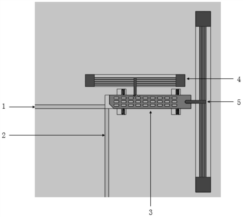
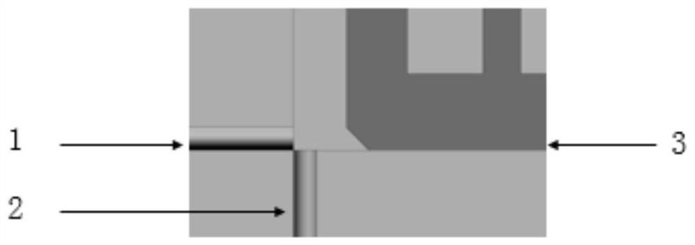
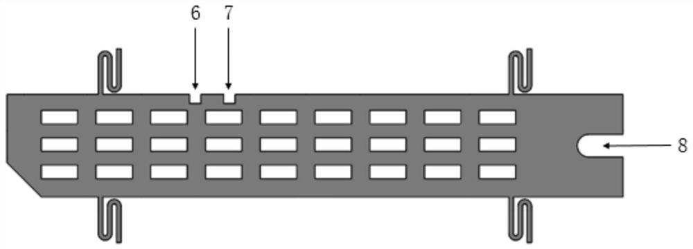
[0029] 1. This embodiment discloses a silicon-based MOEMS optical switch device based on an electrothermally driven micromirror such as figure 1 shown. It is mainly composed of input optical fiber 1, output optical fiber 2, movable micromirror 3, electrothermal safety mechanism 4 and electrothermal driving mechanism 5. The movable micromirror 3 is designed with safety groove 6, positioning groove 7 and driving groove 8; among them, the input The optical fiber 1 and the output optical fiber 2 are fixed optical fibers, which are respectively connected with the light emitting element and the light receiving element; the movable micromirror 3, the electrothermal safety mechanism 4 and the electrothermal driving mechanism 5 are movable parts. On the same SOI (silicon on insulator) silicon wafer, microstructures such as fixed fiber groove, movable micromirror 3, electrothermal safety mechanism 4 and electrothermal driving mechanism 5 are processed, and input optical fiber 1, output ...


PUM


Abstract

The invention discloses a silicon-based MOEMS optical switch device based on an electro-thermally driven micromirror, and belongs to the field of fuse full-electronic safety systems. The silicon-basedMOEMS optical switch device based on the electro-thermally driven micromirror is mainly composed of an input optical fiber, an output optical fiber, a movable micromirror, an electric heating fuse mechanism and an electric heating drive mechanism. The on-off of the MOEMS optical switch is realized by the on-off of a reflective optical path composed of a fixed optical fiber and the movable micromirror. The movement of the movable micromirror is realized by the electric heating drive mechanism. The micromirror is provided with a safety slot and a positioning slot. The electric heating fuse mechanism is inserted into the safety slot and the positioning slot to realize the fuse and positioning of the micromirror, and ensure the on-off state of the MOEMS optical switch. The silicon-based MOEMSoptical switch device solves the poor electromagnetic compatibility of the fuse full-electronic safety system, and has the following advantages of (1) small structural size; (2) good anti-overload capability; (3) good electromagnetic compatibility; 4) reliable operation and good applicability.

Description

technical field [0001] The invention relates to a silicon-based MOEMS optical switch device, in particular to the principle and design method of a silicon-based MOEMS optical switch device based on an electrothermally driven micromirror, and belongs to the technical field of MOEMS optical switches. Background technique [0002] The fuze all-electronic safety system is a high-tech that integrates high-energy detonation technology and microelectronic technology. It adopts a non-flameproof explosion sequence, which fundamentally changes the isolation design idea of ​​the fuze. The all-electronic safety system is different from the traditional fuze safety system, which has the advantages of strong safety, high reliability and rapid action. Although the theoretical security of the all-electronic security system is higher than other types of security systems, there are many electromagnetic safety hazards in the all-electronic security system in practical applications. The extensi...

Claims


Application Information

Patent Timeline
Patent Type & Authority Patents(China)
IPC IPC(8): G02B6/35
Inventor 代俊李凯权吴娇娇常辉熊壮谢晋隋丽石庚辰
Owner BEIJING INSTITUTE OF TECHNOLOGYGY
Learn More