Clamping type radiator

A heat sink, clip-on technology, applied in the direction of modification through conduction heat transfer, cooling/ventilation/heating transformation, electrical components, etc., can solve the problems of waste of energy consumption, difficult production, etc., to improve heat dissipation performance, heat dissipation Excellent performance, the effect of excellent product performance

Inactive Publication Date: 2019-07-09
GUANGZHOU HUAZUAN ELECTRONICS TECH
View PDF0 Cites 2 Cited by
  • Summary
  • Abstract
  • Description
  • Claims
  • Application Information

AI Technical Summary

Problems solved by technology

However, the radiators currently on the market usually need to fix the fins and vapo

Method used


Image

  • Clamping type radiator
  • Clamping type radiator
  • Clamping type radiator

Examples


Embodiment 1

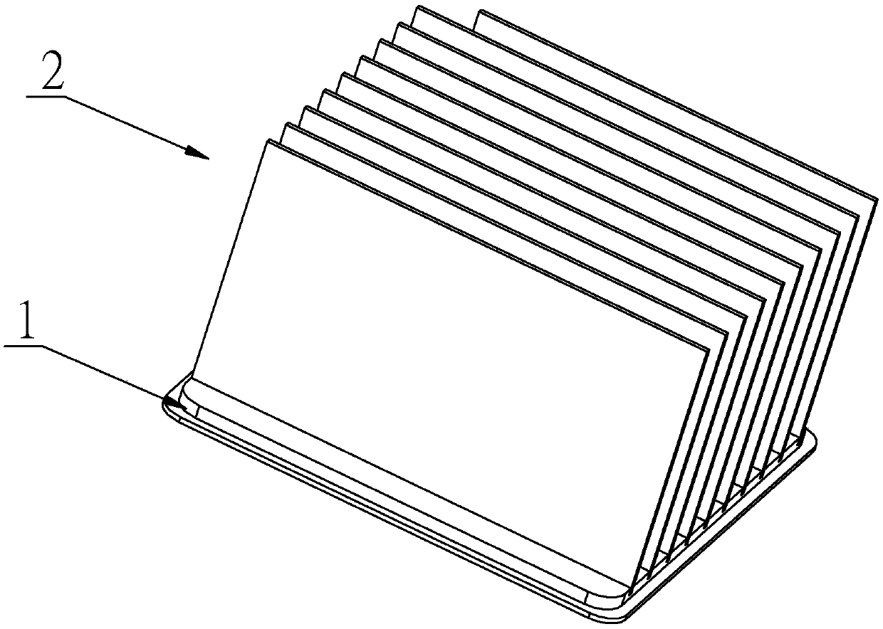
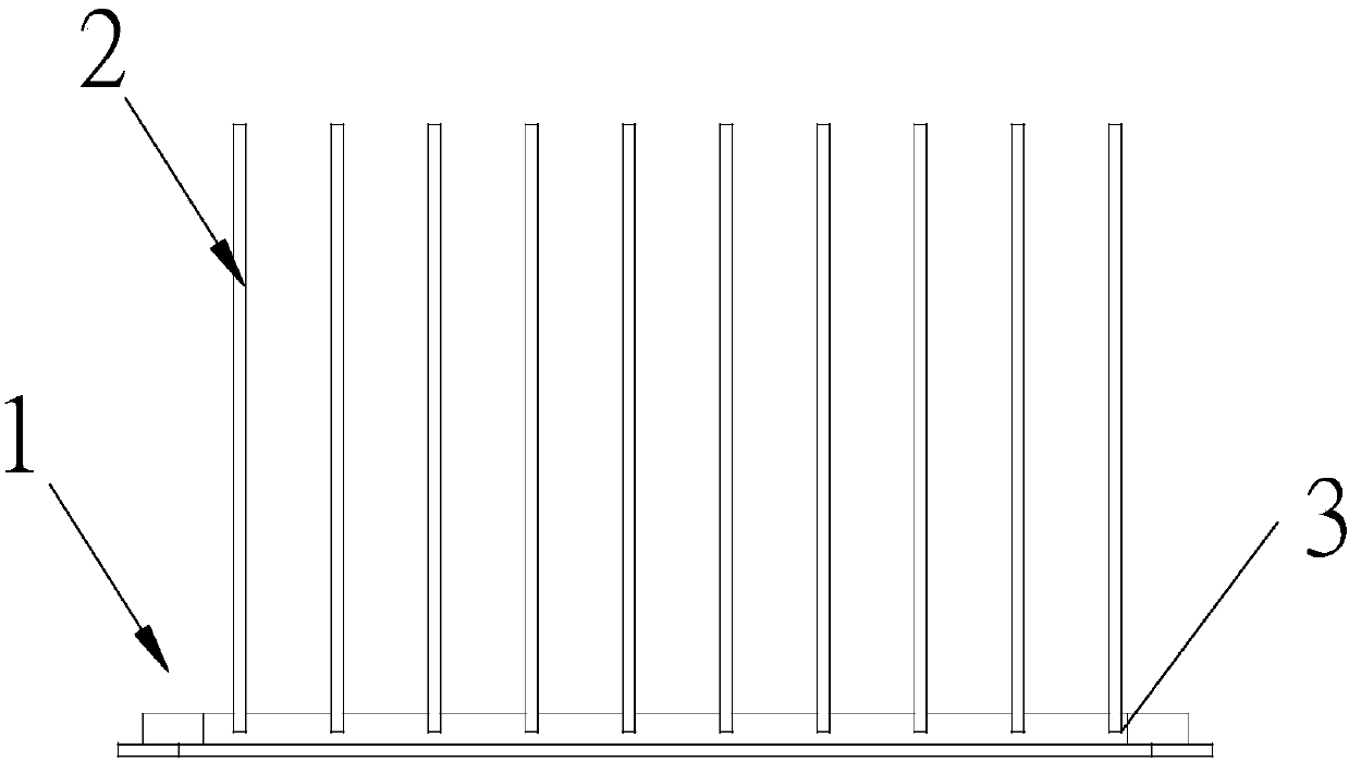
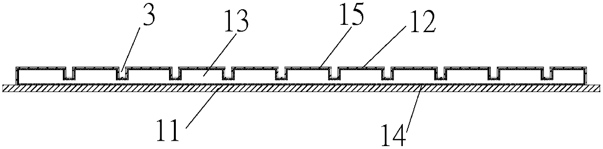
[0029] The invention discloses a clamping radiator, referring to Figure 1 to Figure 4 , including a vapor chamber 1 , preferably a copper vapor chamber, and fins 2 connected to the vapor chamber 1 . Specifically, the vapor chamber includes an evaporating surface 11 and a condensing surface 12, the evaporating surface 11 and the condensing surface 12 form a closed cavity 13, and the closed cavity 13 is filled with a liquid working fluid. The filling amount of the liquid working medium should be greater than or equal to more than half of the volume of the sealed inner cavity, which is not only conducive to the flow of the liquid working medium, but also conducive to increasing the heat dissipation effect. A first capillary layer 14 is sintered on the inner surface of the evaporation surface 11 , and a second capillary layer 15 is sintered on the inner surface of the condensation surface.

[0030] In order to improve the heat diffusion rate from the bottom plate to the capillar...

Embodiment 2

[0033] The invention discloses a clamping radiator, referring to Figure 5 to Figure 8 , including a vapor chamber 1 , preferably a copper vapor chamber, and fins 2 connected to the vapor chamber 1 . Specifically, the vapor chamber includes an evaporating surface 11 and a condensing surface 12, the evaporating surface 11 and the condensing surface 12 form a closed cavity 13, and the closed cavity 13 is filled with a liquid working fluid. The filling amount of the liquid working medium should be greater than or equal to more than half of the volume of the sealed inner cavity, which is not only conducive to the flow of the liquid working medium, but also conducive to increasing the heat dissipation effect. A first capillary layer 14 is sintered on the inner surface of the evaporation surface 11 , and a second capillary layer 15 is sintered on the inner surface of the condensation surface.

[0034] In order to improve the heat diffusion rate from the bottom plate to the capillar...


PUM


Abstract

The invention discloses a clamping type radiator, and aims to provide the clamping type radiator convenient to machine and capable of reducing energy consumption; according to the technical scheme, the clamping type radiator comprises a heat-equalizing plate, wherein the heat-equalizing plate is connected with fins; a plurality of connecting pieces arranged in parallel are arranged on the heat-equalizing plate; a plurality of connecting parts matched with the connecting pieces are arranged on the fins; and the connecting pieces are clamped with the connecting parts.

Description

technical field [0001] The invention relates to heat dissipation of electronic components, in particular to a clamping type heat sink. Background technique [0002] The development of intelligent equipment and the Internet of Things has accelerated the performance requirements of chips. Highly integrated chips will be accompanied by high heat flux density, which seriously affects the response rate of equipment. However, the single-phase cooling technology that only adds fans and cooling fins on the chip can no longer meet the problem of high heat flux density of the existing chip. Compared with traditional air cooling technology and liquid cooling technology, phase change heat transfer technology is one of the most extensively researched thermal control technologies at present, especially with the help of vapor chamber technology of evaporation and condensation of liquid working fluid, the composite heat dissipation model composed of it It can be widely used in heat dissipa...

Claims


Application Information

Patent Timeline
IPC IPC(8): H05K7/20
CPCH05K7/20336H05K7/2039
Inventor 陈平
Owner GUANGZHOU HUAZUAN ELECTRONICS TECH
Why Eureka
Try Eureka