Transient strong electric field measuring system for long air gap discharging

A measurement system and long-air technology, applied in the direction of measuring devices, measuring electrical variables, electromagnetic field characteristics, etc., can solve the problems of small half-wave electric field of the sensor, low stability, and distortion of the measured electric field, etc., and achieve large electric field measurement range and temperature High stability, the effect of meeting the measurement requirements

Inactive Publication Date: 2019-07-12
STATE GRID CORP OF CHINA +3
View PDF7 Cites 5 Cited by
  • Summary
  • Abstract
  • Description
  • Claims
  • Application Information

AI Technical Summary

Problems solved by technology

However, the inventor found in the actual implementation process that traditional electromagnetic field measurement sensors are mostly based on circuit design. The metal device will become the emission source, which will seriously distort the measured electric field and directly affect the quantitative measurement of the electric field strength
The new optical electric field sensor (including the electric field sensor composed of integrated optical waveguide field sensor and discrete optical device) overcomes the interference problem of strong electromagnetic environment. Among them, the integrated optical waveguide field sensor has poor temperature stability because of lithium niobate as the substrate, and the environment The change of temperature will directly affect the accuracy of the measurement, and the electro-optic coefficient of the lithium niobate material is large, resulting in a small half-wave electric field of the sensor, which limits the range of the electric field (on the order of hundreds of kV / m), and for the electric field composed of discrete optical devices Sensor, because of its large size and easy to be affected by external mechanical effects on the optical path, resulting in insufficient accuracy and low stability of electric field measurement

Method used


Image

  • Transient strong electric field measuring system for long air gap discharging
  • Transient strong electric field measuring system for long air gap discharging
  • Transient strong electric field measuring system for long air gap discharging

Examples


Embodiment Construction

[0030] Attached below figure 1 to attach image 3 and Examples describe the present invention in detail, but not as a limitation of the present invention.

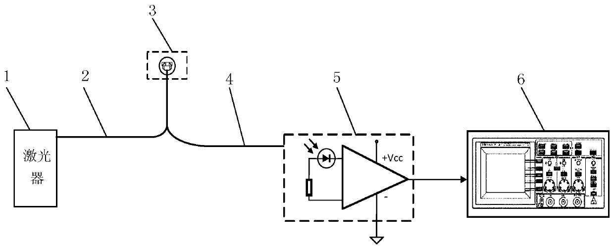
[0031] Such as figure 1 As shown, a transient strong electric field measurement system for long air gap discharge includes: a laser 1 , a first optical fiber 2 , an integrated optical device 3 , a second optical fiber 4 , a photodetector 5 and an oscilloscope 6 . Among them, the laser 1 is used to emit stable monochromatic linearly polarized laser light, the first optical fiber 2 is used to transmit monochromatic linearly polarized laser light and maintain its polarization state, and the integrated optical device 3 is used to control the monochromatic linearly polarized laser light in a transient strong electric field environment. The polarized laser is modulated, the second optical fiber 4 is used to transmit the modulated laser signal to the photodetector, the photodetector 5 is used to collect and process the modulate...


PUM


Abstract

The invention discloses a transient strong electric field measuring system for long air gap discharging. The transient strong electric field measuring system comprises a laser device used for emittinga stable monochromatic linear polarization laser, a polarization maintaining optical fiber used for transmitting the monochromatic linear polarization laser and maintaining a polarization state of the monochromatic linear polarization laser, an integrated optical device used for modulating the monochromatic linear polarization laser in the transient strong electric field environment, and a photoelectric detector used for collecting and processing modulated laser signals to obtain to-be-measured applied electric field strength. The transient strong electric field measuring system has the measuring properties of strong electric field measuring range, low distorsion, anti-electromagnetic interference, high-frequency band and high stability, and has the advantages of small size, high measuring precision and the like, and the practical demand for quantitative measuring of the space electric field in the long air gap discharging process is met.

Description

technical field [0001] The invention relates to a transient strong electric field measurement system for long air gap discharge, belonging to the technical field of transient strong electric field measurement for long air gap discharge. Background technique [0002] The study of long air gap discharge mechanism is the theoretical basis for the design of electrical equipment insulation structure and selection of insulation parameters. Due to the limitation of measurement methods, it has been impossible to accurately and quantitatively measure the electric field strength near the discharge channel. In most cases, numerical simulation is chosen for research. . There are two kinds of electric field measuring devices that exist at present: the traditional electromagnetic field measuring sensor (antenna) and the new optical electric field sensor. However, the inventor found during the specific implementation process that most of the traditional electromagnetic field measurement s...

Claims


Application Information

Patent Timeline
Patent Type & Authority Applications(China)
IPC IPC(8): G01R29/08
CPCG01R29/0871
Inventor 樊星陈维江何天宇张乔根向念文边凯文韬董冰冰杜斌
Owner STATE GRID CORP OF CHINA
Why Eureka
Try Eureka