
A method for building a full three-dimensional coupled model of a reactor u-tube steam generator
A steam generator and coupling model technology, applied in the direction of instrumentation, design optimization/simulation, computer-aided design, etc., to achieve model independence, ensure model calculation accuracy, and wide versatility
- Summary
- Abstract
- Description
- Claims
- Application Information
AI Technical Summary
Problems solved by technology
Method used
Image

Examples
Embodiment Construction
[0046] Below in conjunction with accompanying drawing, the present invention is described in further detail:
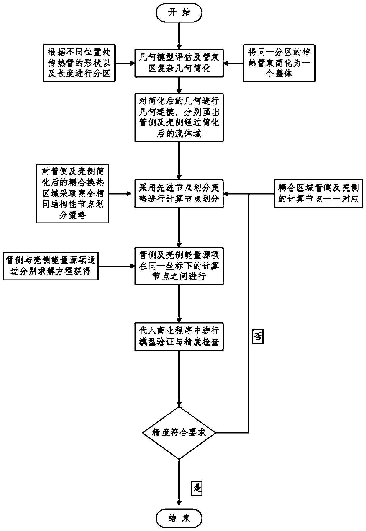
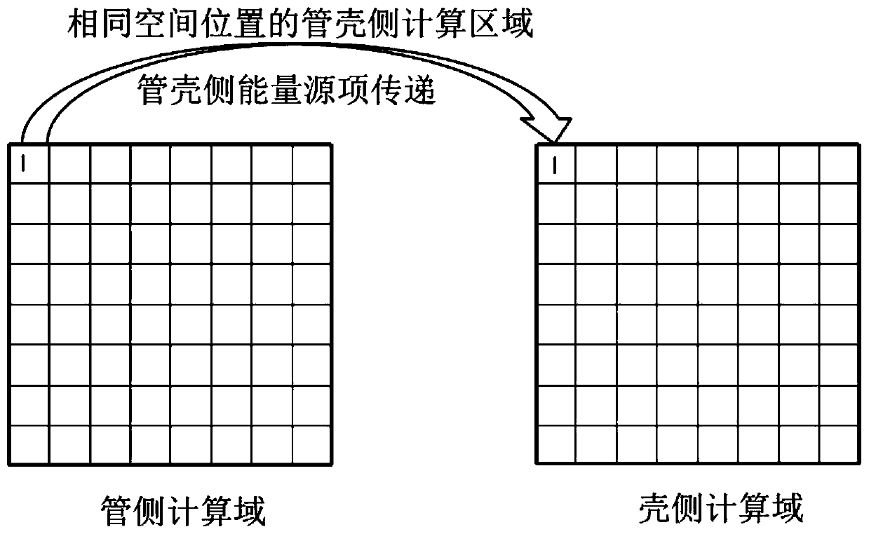
[0047] first according to figure 1 The flow chart of the establishment of the full three-dimensional thermal coupling model of the reactor U-shaped tubular steam generator provided, the model establishment method proposed in the present invention mainly includes the following parts: 1. simplification of the geometric model of the tube bundle area; 2. 1. Establishment of geometric model of porous medium on the secondary side; 3. Division of three-dimensional calculation nodes on the primary and secondary sides; 4. Calculation of energy source items on the primary and secondary sides; 5. Connection of primary and secondary side calculation nodes in the heat exchange coupling area Point processing and energy source item data transfer between primary and secondary nodes; 6. Coupling model inspection and calibration.
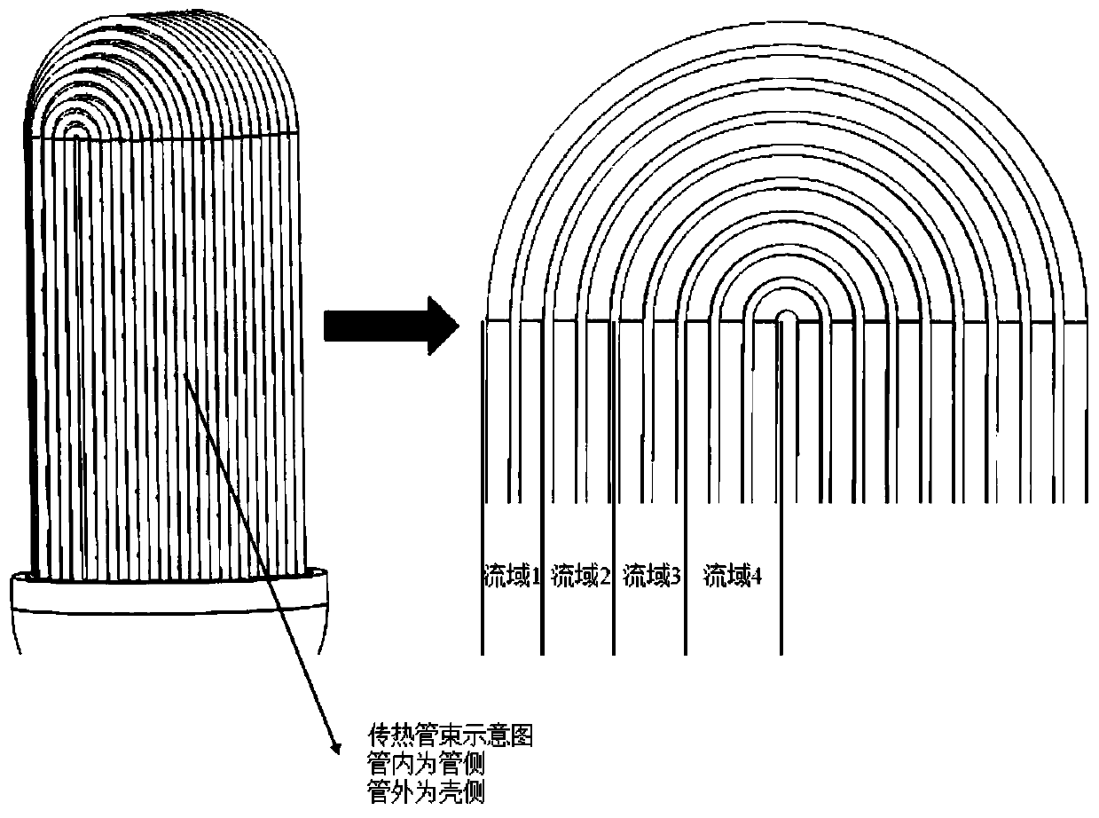
[0048] according to figure 2 The given geometric si...
PUM
 Abstract
Description
Claims
Application Information