
Manufacturing method of composite screen printing plate

A technology of composite screen and production method, which is applied in the field of printing components, can solve the problems of plate emulsion falling off, friction and easy wear, slurry leakage, poor emulsion wear resistance, etc., and achieves the limitation of high-precision compression and narrow line width, and is not easy to wear Effects of holes and improved printing life

Inactive Publication Date: 2019-07-23
SUZHOU WOSUTE ELECTRONICS MATERIALS CO LTD
View PDF8 Cites 10 Cited by
  • Summary
  • Abstract
  • Description
  • Claims
  • Application Information

AI Technical Summary

Problems solved by technology

The screen produced by this method has certain limitations: 1. The resolution of the photosensitive emulsion under the action of light is not easy to grasp, and the flatness of the edge of the line after exposure and development is not good, and it is easy to affect the printing quality of the line when used; 2. The adhesion between the emulsion and the steel mesh yarn is not good, and it is easy to cause the plate emulsion to fall off after exposure and development, which greatly affects the plate-making yield; 3. The abrasion resistance of the emulsion is not good, and the friction with the substrate during printing is easy to wear and leak, which affects Surface printing quality and service life; 4. The lines are greatly affected by the stability of light energy during exposure, which can easily lead to uneven line thickness, which affects the production yield during mass production and affects printing stability during use; 5. Emulsion penetration Due to the influence of ink properties, the printing line cannot be narrowed to a narrower range, which cannot meet the requirements of high-precision fine line printing

Method used


Image

  • Manufacturing method of composite screen printing plate
  • Manufacturing method of composite screen printing plate

Examples


Embodiment Construction

[0022] The following will clearly and completely describe the technical solutions in the embodiments of the present invention. Obviously, the described embodiments are only some of the embodiments of the present invention, rather than all the embodiments. Based on the embodiments of the present invention, all other embodiments obtained by persons of ordinary skill in the art without making creative efforts belong to the protection scope of the present invention.

[0023] Embodiments of the invention include:

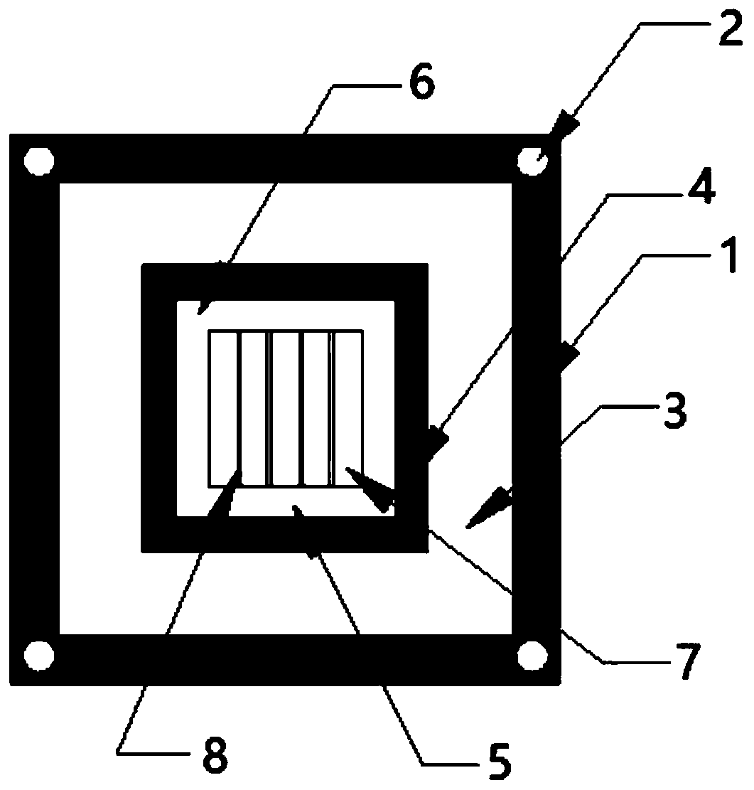
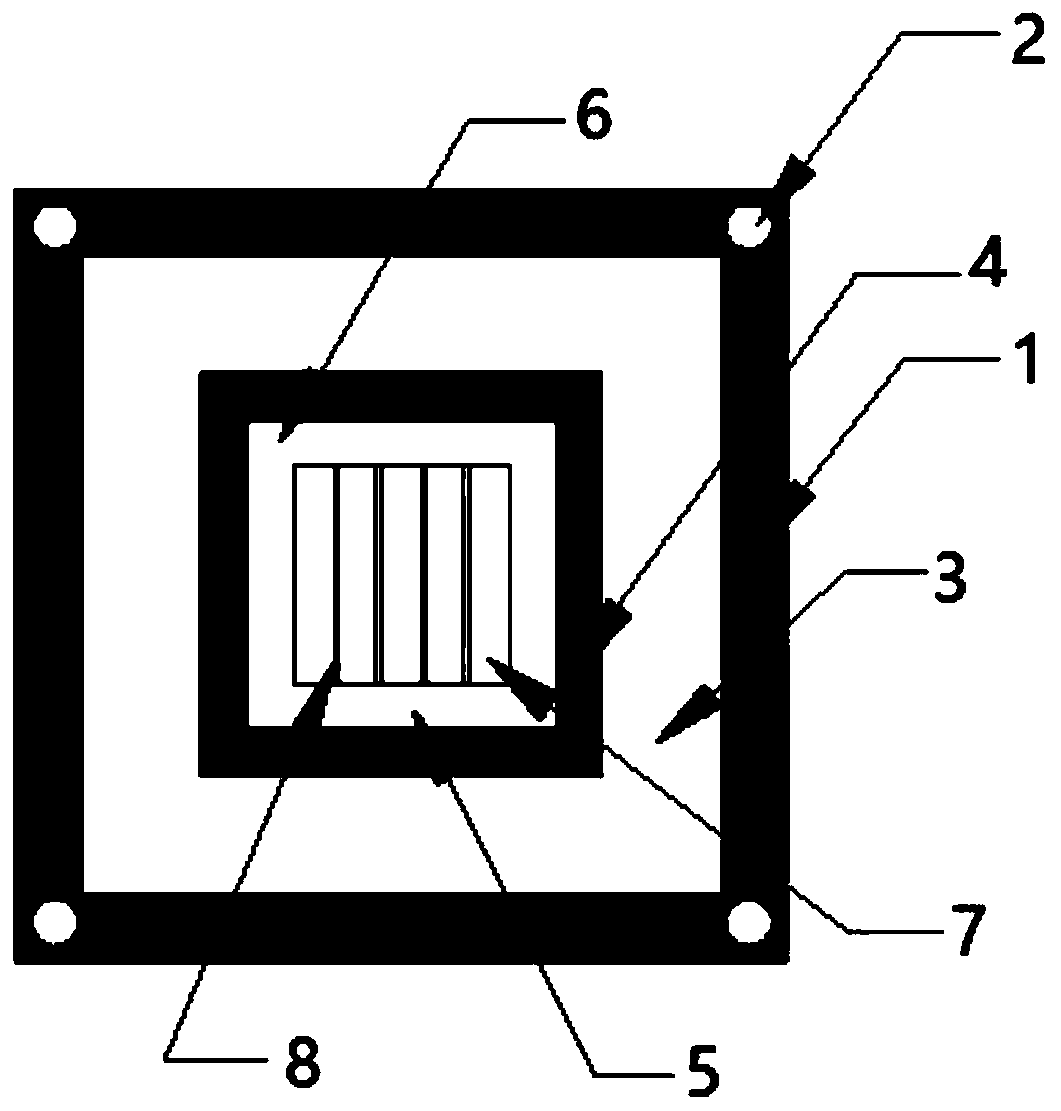
[0024] Such as figure 1 As shown, the composite screen includes screen frame 1 , through hole 2 , polyester mesh 3 , composite area 4 , steel mesh 5 , polymer composite layer 6 , pattern area 7 and film layer lines 8 .

[0025] A method for making a composite screen comprising the following specific steps:

[0026] 1) Stretching and compounding: Stretch the polyester mesh first, fix the polyester mesh on the frame to form a polyester mesh after standing still, and then...


PUM

PropertyMeasurementUnit
Thicknessaaaaaaaaaa

Abstract

The invention discloses a manufacturing method of a composite screen printing plate. The manufacturing method comprises the following steps of 1) screen pulling and compounding; 2) film layer manufacturing; 3) coating an adhesive layer; 4) coating a film; 5) drying; 6) laser; 7) cleaning; and 8) detection and packaging. By means of the mode, the manufacturing method of the composite screen plate has the advantages that when the screen printing plate is used, the film layer is not easy to wear and break, the printing life is prolonged by one time or more, the printing life of a conventional plate-making screen printing plate is averagely increased by about 50 thousand, the average energy of the screen printing life prepared by the method can reach 100 thousand or above and even higher, theprinting line at the later stage is not expanded, and the efficiency of the battery piece is obvious; and the manufactured screen printing plate is better in ink permeability, so that the limitation of the high-precision narrow line width can be greatly reduced, on the basis of the same type of ink printing, the width of the designed line can be compressed by 2-5 microns, the printing is good, theline type is good, and therefore the efficiency of the battery piece is obviously improved.

Description

technical field [0001] The invention relates to the technical field of printing components such as solar cells and high-precision electronic components, and in particular to a method for making a composite screen. Background technique [0002] With the increasing demand for energy, energy issues have increasingly become a major issue restricting the development of the international society and economy, which prompts people to continue to explore new energy sources, among which solar energy research occupies an important position. As one of the core technologies of solar energy research, solar cells have also developed rapidly in recent years. Improving the conversion efficiency of solar cells is the main research object of solar cells at present. In addition to the selection and optimization of battery substrate materials and the improvement of cell manufacturing processes, etc. In addition to the requirements, the conversion efficiency of solar cells can also be improved by...

Claims


Application Information

Patent Timeline
IPC IPC(8): B41C1/14B41N1/24B41N1/04B41N1/12B41N3/06B41N3/00
CPCB41C1/14B41C1/145B41C1/147B41N1/04B41N1/12B41N1/24B41N1/247B41N3/006B41N3/06
Inventor 王玉彬史建新张德祥余道瑶
Owner SUZHOU WOSUTE ELECTRONICS MATERIALS CO LTD
Learn More