A method to cope with the thermal load shock in the late stage of blast furnace operation

A heat load and blast furnace technology, applied in the direction of cooling devices, etc., can solve problems such as furnace skin crack expansion, furnace skin stress concentration, gas leakage, etc.

Active Publication Date: 2020-09-11
WUHAN UNIV OF SCI & TECH
View PDF8 Cites 0 Cited by
  • Summary
  • Abstract
  • Description
  • Claims
  • Application Information

AI Technical Summary

Problems solved by technology

And the installation method of this kind of cooling column is often neither planned nor considering the efficiency of the installation. It is just installed where it is damaged. Sometimes a severely damaged blast furnace can install hundreds of cooling columns at most. It is basically a "headache doctor". , the passive way of treating foot pain"
[0004] The document "Li Jichang, Zhang Yun, Wang Qingxue. Cooling column technology introduction and independent development practice[J]. Gansu Metallurgy, 2012, 34(6):1-6." lists more than 200 cooling columns installed in the first generation furnace Columns, these cooling columns were installed in batches and in stages, without any plan or planning. Due to the random installation, the strength of some furnace shells decreased, the furnace skin became red and deformed, and the gas leaked seriously.
The literature "Ju Qinzhang. Optimization of the cooling system of Baosteel No. Part of the cooling column was also used in the later period. The optimization of the cooling column was also not considered during the installation process. The installation was relatively random, and the strength of the furnace skin was reduced due to the installation, which also caused large-area cracking of the furnace skin when the heat load in the furnace changed drastically. , deformation
It is fully reflected in the document "Chen Kunnan, "Investigation and Analysis on the Use Effect of Copper Cooling Column", Ironmaking, May 2003", which analyzed the 2500m 3 The blast furnace uses copper cooling columns to repair the condition of the damaged stave. After the shutdown, it is found that if the stave remains are no longer in the case of serious damage to the stave, the copper cooling column is installed at this time, and the copper cooling column is only supported in isolation. On the furnace shell, due to the large-scale damage of the cooling system, the furnace shell and the furnace material are in direct contact. It is difficult for the poured refractories to wrap the copper cooling column well, and it is also difficult to form a layer on the inner surface of the furnace shell to grout with other copper cooling columns. The protective layer connected to the material, the inner surface of the furnace shell without the protective layer is difficult to be exported through the cooling water of the copper cooling column due to the heat generated by the gas flow, molten slag iron and furnace material during production, and the heat carried by the high-temperature gas is still conducted to the furnace. In this case, due to the instability of the slag skin, a part of the copper cooling column exposed to the furnace charge is easily eroded and scoured by the furnace charge, gas flow, and molten slag and iron. Bending deformation and damage
[0005] The above documents are all based on avoiding the damage of the furnace shell and maintaining a certain cooling capacity when the blast furnace is damaged. The installation of the cooling column is generally passive with the damage of the cooling wall of the furnace body. The number and location of the installation are not optimized in advance. The cooling column is only an expedient measure, and its cooling capacity is generally smaller than that of the original cooling system. Due to the randomness of installation, the opening positions of the furnace skin are chaotic, and the stress of the furnace skin is concentrated, which often causes cracks and expansion of the furnace skin, causing huge hidden dangers to production. , when encountering fluctuations in furnace conditions during blast furnace production, the area where the cooling column is installed is simply unable to resist fluctuations in large heat shocks, and objectively reduces the role of the cooling column. The current life of the cooling column is only about 6 to 10 months. This results in frequent shutdown of the blast furnace, low production efficiency and high consumption

Method used


Image

  • A method to cope with the thermal load shock in the late stage of blast furnace operation

Examples


Embodiment 1

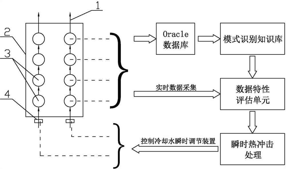
[0044] Depend on figure 1 It can be seen that a method to deal with the thermal load shock in the later stage of blast furnace operation includes the following steps:

[0045] ⑴Material lowering line: In the case of a large number of damaged staves, clean up the remaining stave wall, and lower the material line below the remaining stave elevation (in this embodiment, 3200m 3 Take the blast furnace as an example, the height of the shaft is 17.5m, the height of the bosh is 2m, and the height of the waist is 3m), so as to facilitate the installation and construction of the blast furnace cooling column 3;

[0046] (2) Furnace skin opening: according to the characteristics of the damaged area, use a drilling machine to make holes on the furnace skin around the damaged area. 3 The total thickness of the furnace skin and cooling wall of the blast furnace is 400㎜~500㎜), that is, the depth of the opening should be such that the cooling column 3 touches the furnace material after insta...

Embodiment 2

[0075] The cooling column group of this embodiment is a row of 4 cooling columns 3 on one block 2, a total of 8 cooling columns 3 in the left and right columns, and a total of 16 cooling columns 3 in two columns connected up and down adjacent to each other to form a cooling column. column group.

[0076] The rest are the same as embodiment 1.

Embodiment 3

[0078] The cooling column group of this embodiment is a row of 4 cooling columns 3 on one block 2, and three blocks 2 connected up and down successively are installed with a total of 12 cooling columns 3 in one column to form a cooling column group.

[0079] The rest are the same as embodiment 1.


PUM


Abstract

The invention discloses a method for coping with heat load impacts in the later period of the service life of a blast furnace. The method is characterized by comprising the steps of material line reducing, furnace shell hole opening, cooling column set mounting, cooling column set connecting, mounting of a cooling water instant adjusting device, building of a mode recognition unit, building of a data feature evaluation unit, problem processing and knowledge base updating. According to the method, the mounting positions and the mounting mode of cooling columns are optimized, the cooling columnset formed by the multiple cooling columns is mounted in the cooling wall damage area at a time in the later period of the service life, the cooling capacity is doubled, the cooling capacity is improved so as to over the defect that the cooling capacity of a single cooling column is insufficient, and the problem of stress concentration of a furnace shell is avoided; and a make-up water adjusting valve is mounted on a water inlet pipe of the cooling column set, the partial cooling water flow is increased when the blast furnace is faced with large heat load impacts, large-heat instant impacts onthe lower portion of the blast furnace are responded to so as to avoid the situation that heat is concentrated to impact on the furnace shell, red turning and cracking of the furnace shell are avoided, and it is ensured that the blast furnace runs stably and smoothly.

Description

technical field [0001] The invention relates to iron and steel smelting equipment, in particular to a blast furnace, in particular to a method for dealing with the impact of heat load in the later stage of blast furnace operation. Background technique [0002] As a smelting equipment, the blast furnace is often faced with a large number of cooling wall burns, production decline, and serious gas leakage problems in the later stage of the furnace operation. The stave is composed of the stave body and the cooling water pipe cast inside. Blast furnace production is a link embedded in the iron and steel complex. Long-term maintenance of a large blast furnace will have a great impact on the entire iron and steel enterprise, especially long-term unplanned maintenance will seriously interfere with the operation of the enterprise and cause huge losses. [0003] At present, the generally more effective method is to install effective cooling equipment——cooling column at the damaged pa...

Claims


Application Information

Patent Timeline
Patent Type & Authority Patents(China)
IPC IPC(8): C21B7/10
CPCC21B7/10
Inventor 李佳张亮唐志文
Owner WUHAN UNIV OF SCI & TECH
Why Eureka
Try Eureka