Three-rotor flowmeter made of composite material
A composite material and three-rotor technology, applied in the field of flow meters, can solve the problems of short life, loud noise, and unstable appearance, and achieve the effects of long life, low noise, and stable rotation
- Summary
- Abstract
- Description
- Claims
- Application Information
AI Technical Summary
Problems solved by technology
Method used
Image
Examples
Embodiment 1
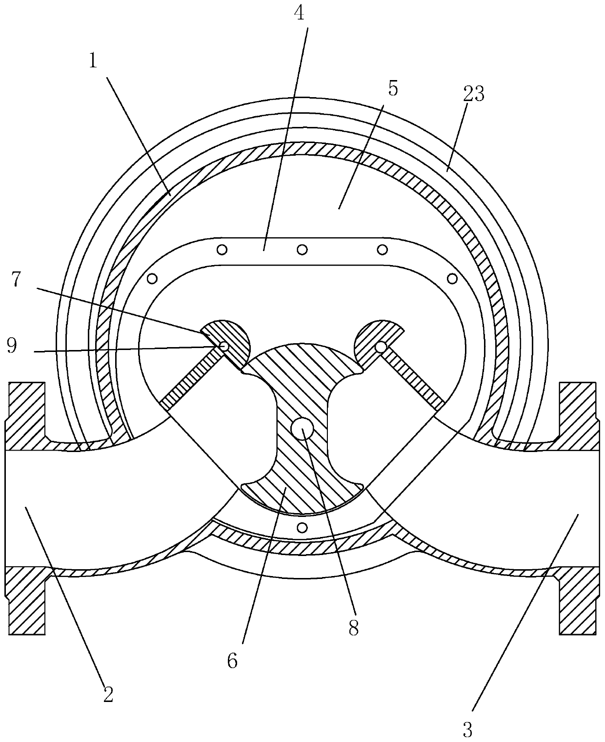
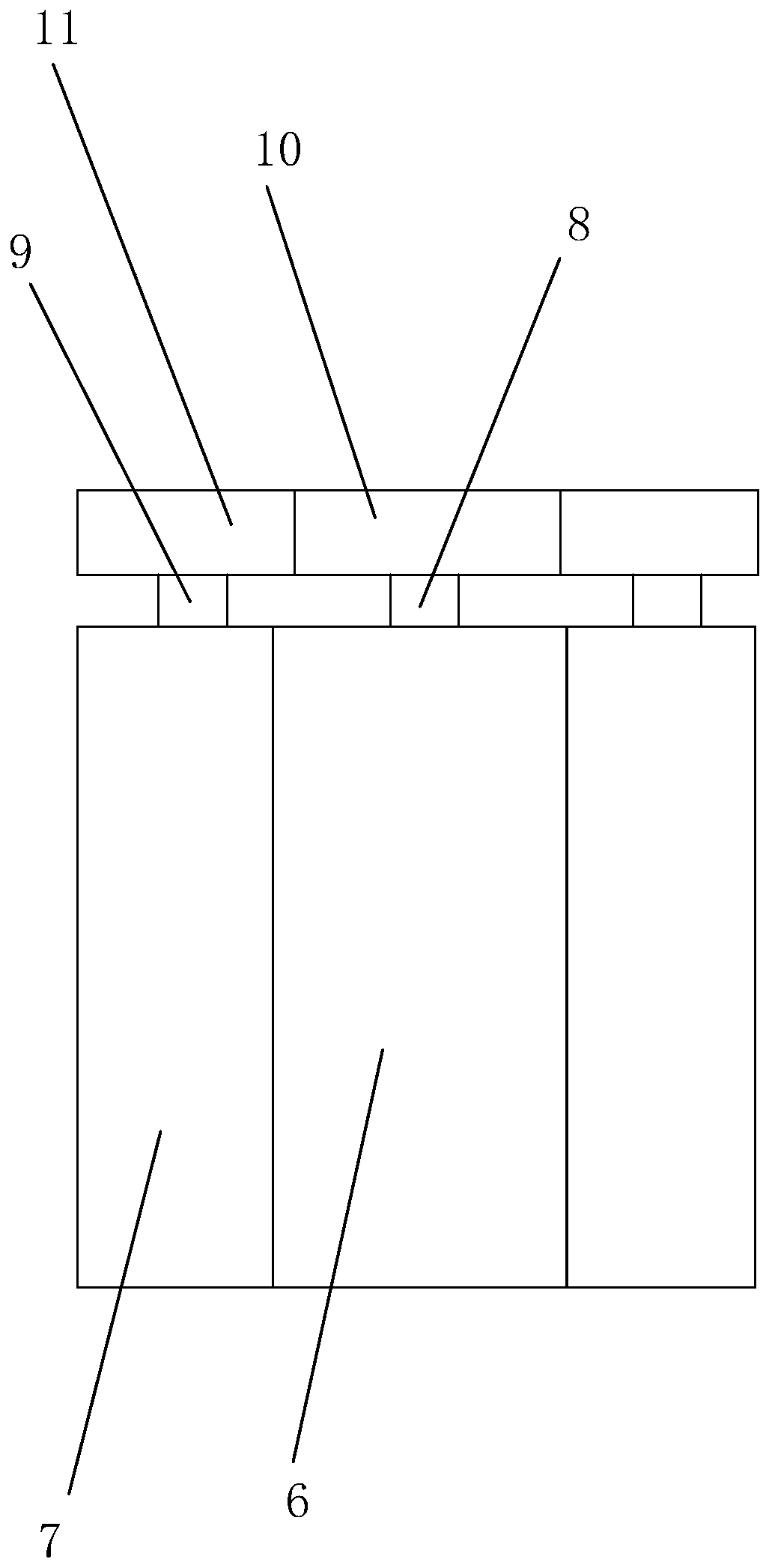
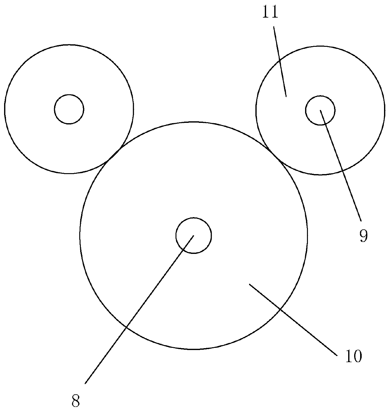
[0034] Embodiment 1: A kind of three-rotor flowmeter that adopts composite material, such as Figure 1-Figure 7 As shown, it includes an outer casing 1, the outer casing 1 is integrally connected with an inlet pipe 2 and an outlet pipe 3, an inner casing 4 is installed inside the outer casing 1, and the inner casing 4 and the outer casing 1 are connected to each other. There is a gap 5, the outer casing 1 and the inner casing 4 are connected by bolts, the inner casing 4 is provided with a large rotating shaft 8 and a small rotating shaft 9, and the large rotating shaft 8 is sleeved with a large rotor 6, so The small rotating shaft 9 is sleeved with a small rotor 7, the top of the large rotating shaft 8 is sleeved with a large gear 10, and the top of the small rotating shaft 9 is sleeved with a small gear 11 meshing with the large gear 10. The large rotating shaft 8 and the large rotor 6 are fixedly connected by bolts, the small rotating shaft 9 and the small rotor 7 are connec...
Embodiment 2
[0047] Embodiment 2: The difference with Embodiment 1 is that,
[0048] According to parts by weight, the large rotor and the small rotor are the same component, including the following components: 75 parts of polytetrafluoroethylene, 25 parts of molybdenum disulfide, 15 parts of carbon black, 22 parts of silicon carbide, 33 parts of glass fiber, 18 parts of chromium carbide, 20 parts of superfine styrene-butadiene rubber, 15 parts of calcium carbonate powder, and 8 parts of aluminum-zirconium coupling agent.
[0049] The particle size of the ultrafine styrene-butadiene rubber is selected from 12-14 microns.
[0050] A method for preparing a large rotor, comprising the steps of,
[0051] Step A: Weigh 33 parts of glass fibers of equal length, and perform surface coupling treatment with 8 parts of aluminum-zirconium coupling agent;
[0052] Step B: Weigh 75 parts of polytetrafluoroethylene, 25 parts of molybdenum disulfide, 15 parts of carbon black, 22 parts of silicon carbid...
Embodiment 3
[0054] Embodiment 3: The difference with Embodiment 1 is that
[0055] According to parts by weight, the large rotor and the small rotor are the same component, including the following components: 80 parts of polytetrafluoroethylene, 30 parts of molybdenum disulfide, 20 parts of carbon black, 25 parts of silicon carbide, 35 parts of glass fiber, 20 parts of chromium carbide, 25 parts of superfine styrene-butadiene rubber, 20 parts of calcium carbonate powder, and 10 parts of aluminum-zirconium coupling agent.
[0056] The particle size of the ultrafine styrene-butadiene rubber is selected from 12-14 microns.
[0057] A method for preparing a large rotor, comprising the steps of,
[0058] Step A: Weigh 35 parts of glass fibers of equal length, and perform surface coupling treatment with 10 parts of aluminum-zirconium coupling agent;
[0059] Step B: Weigh 80 parts of polytetrafluoroethylene, 30 parts of molybdenum disulfide, 20 parts of carbon black, 25 parts of silicon carbi...
PUM
 Abstract
Description
Claims
Application Information
 - R&D
- Intellectual Property
- Life Sciences
- Materials
- Tech Scout
- Unparalleled Data Quality
- Higher Quality Content
- 60% Fewer Hallucinations
Browse by: Latest US Patents, China's latest patents, Technical Efficacy Thesaurus, Application Domain, Technology Topic, Popular Technical Reports.
© 2025 PatSnap. All rights reserved.Legal|Privacy policy|Modern Slavery Act Transparency Statement|Sitemap|About US| Contact US: help@patsnap.com


