
In-situ high/low-temperature indentation testing device applied to cone-beam CT imaging

A CT imaging and testing device technology, applied in measurement devices, testing material hardness, instruments, etc., can solve problems such as the inability to unify the microscopic deformation mechanism and mechanical properties of materials, and achieve compact structure, extended temperature range, and novel ideas.

Pending Publication Date: 2019-07-23
JILIN UNIV
View PDF2 Cites 6 Cited by
  • Summary
  • Abstract
  • Description
  • Claims
  • Application Information

AI Technical Summary

Problems solved by technology

Another example is the Chinese patent (CN104697872A) involving a continuous temperature-adjustable high-vacuum low-temperature micro-nano indentation test method and device. A low-temperature thermostat with liquid nitrogen and a variable-temperature stage with a built-in heater can be used to achieve 77K- The continuous contact temperature change of 500K greatly expands the test temperature range, but due to the lack of in-situ observation means, it is impossible to unify the microscopic deformation mechanism and mechanical properties of the material

Method used


Image

  • In-situ high/low-temperature indentation testing device applied to cone-beam CT imaging
  • In-situ high/low-temperature indentation testing device applied to cone-beam CT imaging
  • In-situ high/low-temperature indentation testing device applied to cone-beam CT imaging

Examples


Embodiment Construction

[0027] The detailed content of the present invention and its specific implementation will be further described below in conjunction with the accompanying drawings.

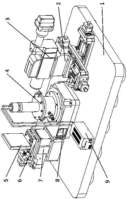
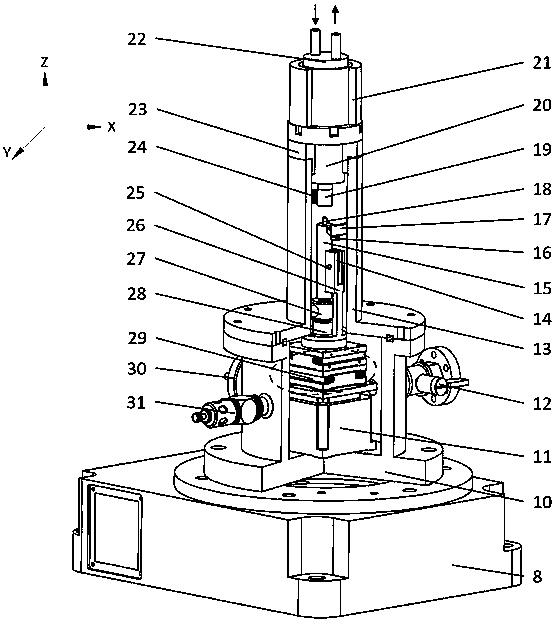
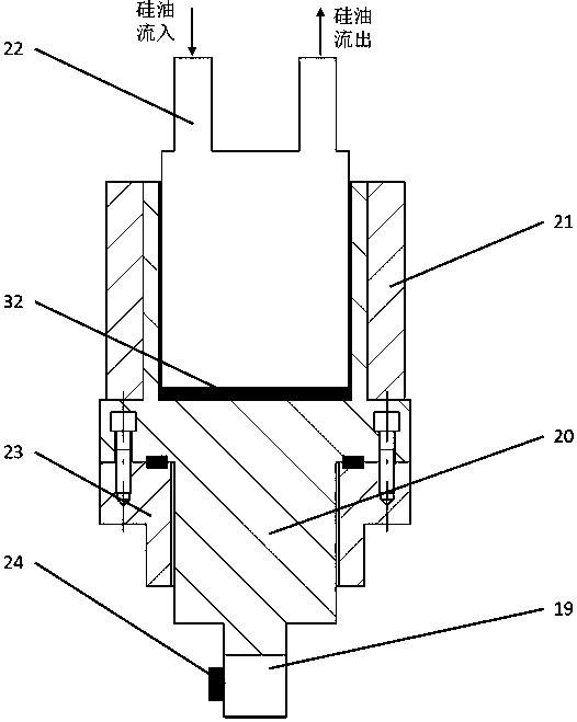
[0028] see Figure 1 to Figure 5 As shown, the in-situ high / low temperature indentation testing device for cone-beam CT imaging of the present invention organically combines CT non-destructive testing technology and indentation testing technology; under the dynamic monitoring of cone-beam CT imaging unit Carry out in-situ nanoindentation tests in high / low temperature environments. The invention can carry out micro-nano indentation test for the change of mechanical properties of materials in high / low temperature environment of -50°C~120°C, and can also perform in-situ observation and three-dimensional imaging of the microscopic deformation and damage process of materials under the action of high stress and strain , which provides a new technical means for studying the physical and mechanical properties of sample m...


PUM


Abstract

The invention relates to an in-situ high / low-temperature indentation testing device applied to cone-beam CT imaging and belongs to the field of testing of mechanical-electrical integration precision scientific instruments and materials. The in-situ high / low-temperature indentation testing device comprises a cone-beam CT imaging unit, a high / low-temperature indentation testing unit, an electric rotating platform, a vibration isolation platform and a silicone oil temperature control device, wherein the cone-beam CT imaging unit, the electric rotating platform and the silicone oil temperature control device are mounted on the vibration isolation platform; a high / low-temperature indentation testing unit is fixed on the electric rotating platform and comprises a high / low-temperature loading submodule, a precision loading and detecting submodule and a vacuum guaranteeing submodule. The in-situ high / low-temperature indentation testing device is capable of carrying out in-situ micro-nano indentation testing in the high / low-temperature environment with the temperature from 50 DEG C below zero to 120 DEG C under dynamic monitoring of the cone-beam CT imaging unit, carrying out in-situ observation and three-dimensional imaging of micro deformation and damage processes of the materials under the actions of high stress and high strain, and providing an effective technical manner for revealing mechanics behaviors of the materials under thermal coupling loading conditions and constitutive relations of microstructure changes of the materials.

Description

technical field [0001] The invention relates to the fields of mechatronic precision scientific instruments and material testing, in particular to an in-situ high / low temperature indentation testing device for cone-beam CT imaging. It can realize in-situ micro-nano indentation test under high / low temperature environment of -50°C-120°C, which provides a new technical means for revealing the mechanical behavior of materials and the constitutive relationship of microstructure changes under the condition of mechanical and thermal coupling loading. Background technique [0002] In-situ micro-nano mechanical testing technology refers to the process of testing the mechanical properties of the tested materials at the micro-nano scale, using imaging instruments such as electron microscopes, atomic force microscopes or optical microscopes to measure the microscopic deformation, damage and failure of materials under load. The testing technology for real-time dynamic monitoring of the pr...

Claims


Application Information

Patent Timeline
IPC IPC(8): G01N3/54
CPCG01N3/54G01N2203/0003G01N2203/0019G01N2203/0051G01N2203/0082G01N2203/0226G01N2203/0228G01N2203/0244G01N2203/0617G01N2203/0647G01N2203/0682
Inventor 王顺博张建海赵宏伟周水龙张世忠孟凡越赵久成
Owner JILIN UNIV
Learn More